Here you can find some detailed informations about the project sometimes about other things I'm working on.
Under the date of the diary entry you can see the theme for the entry.
Most of the ppl fall asleep during read or after ;) it's more or less for me for later readings...
| 06.12.2023 ultraDev+ rev.b |
Isn't that beautiful?:
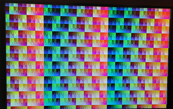
Ok a standard checkboard pattern but this showed me the HDMI output of ultraDev+ is working. That made my day :) The fully built up PCB you can see here on the left (rev.b) on the left the first (rev.a): 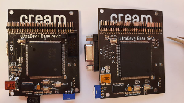
As you can see some slight differences on the rev.b PCB on the left side is the new HDMI section. That was a real challenge to layout this on the limited available area. And the upper picture proofs the stuff is working. Cool. The PCB arrived one week ago unforunately because of a cold I wasn't able to build it up earlier. Build up took a while but this is normal. The first build up needs always a bit of time like checking if everything is good to solder and no bigger componets placements mistakes are done. All is fine. Until now I only found some solder mask and text bugs on the PCB but no big deal. So over XMas I have something to play with. I really hope the rest is working fine. HDMI was the most complex new feature which is working fine. That's pretty cool. One week left and my traditinal XMas vacation starts. Nice :) |
| 17.11.2023 ultraDev+ rev.b PCB |
The PCB are done and already send yesterday. Currently the PCBs are in Hong Kong. With some luck they arrive next week. Niceness. I discovered a small bug in the new revision in the layout: 
Nothing big just a problem in the solder mask. If you look on the lower left there is too much copper visible. Hm anyway the PCB will still work. Maybe I need to use some black paint anyway... |
| 13.11.2023 ultraDev+ rev.b PCB |
Today I checked the new PCB again and did the last placement test means I print out both sides of the PCB on paper and try
to place the all bigger components. This is a quite important step since you not always see in the layout prg watch a problem is. Today I saw because of the check the sd card holder is too close the on/off switch. Good that I checked this. Next step is to generate the so called gerber files. These files are needed by the PCB manufacturer to produce the PCB. Basically For each layer (upper/lower copper, drills and silkscreen) a file. Next step is to upload the gerber files to the company and pray they accept the files. This time is was quite nervous because all other PCBs I did before I haven't been at the absolut max. capabilities of the PCB manufacturer. Capabilities like minimal track width space or minimal drills for vias. This time I was but it seems they accepted the PCB and they already generating the data for production. Puh... In about 14 days I should have the PCB yay... Time for a project switch ;) |
| 08.11.2023 ultraDev+ rev.b |
Continued the new layout for rev.b and I was able to route the HDMI stuff now after skipping the termination resistors.
The longest track is about 40mm means the rise time could be about 1.2ns I think this will work. The PCB is not fully checked but my plan is to do this as soon as possible. I want to have the PCBs here over XMas so can work a bit on it ;) This is how it looks like: 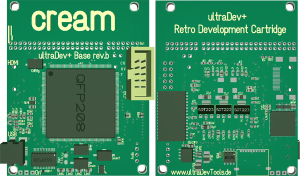
As you can see around the HDMI circut (left picture on the left and right picture on the right) there isn't much space to route the tracks. There are about 35 tracks from the FPGA to the HDMI chip. That took ages on a 2 layer PCB to route. So the new stuff is in rev.b:
My new idea would make it possible to share volumes with quite a few gigs. But let's see first the PCB needs to be done... So I hope I can finish the PCB until end of the week. |
| 24.10.2023 Life ultraDev+ HDMI |
Well life catched me again. I exchanged a few heaters in my house. Unforunately this took alot longer than expected.
Yeah I could have done this next year but anyway I wanted to have this done before the winter... Anyway. Ah well routing the connections and componets for the new HDMI port isn't easy. There is so limited place and I do not want change to a 4 layer PCB. And even with 4 layers it's almost not possible. Esp. with HDMI you should keep the lines as short as possible. Hm the biggest problem are some resister networks for the lines from the FPGA to the HDMI chip. 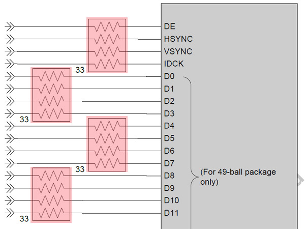 As you can see each line needs a resistor. That takes alot of space and I only have about 1,3 cm on the left of the FPGA. In all I need 4 resistor networks with 4 resistors each means 16 x 33 ohm resistors. This is quite alot on this small place At weekend I was thinking mh do I really need these resistors? What happens when I just leave them out 33 ohm for each line sounds odd. How can I proove I do not need them? I'll just note down my thoughts here if I really need these resistors. First of all I did not study electronics maybe my explanations aren't correct. It's just how I understood it. If something is wrong tell me ;) As you maybe know transfering digital signals over a line can be a problem when it gets too long. The result can be a wrong signal at the reiceiver side. 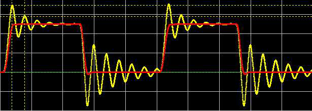 (image is from somewhere on the net forgot from where...) A too long line will create reflections and this is how they look like. You surely can imagine a sensitive receiver of that signal will result in a wrong signal. The resistors in the upper schematics are termination resistors which are trying to reduce these reflections. Alot of ppl are thinking a fast signal causes problems with too long lines but this is wrong. It is not the speed of the transfer it is the rise time of the signal which causes reflections. A line is considered electrically too long when the simple propagation delay of the line is greater than approximately 1/6 of the minimum signal rise time. (from mikrocontroller.net) Propagation speed of electrical signals is 21cm/s. To calculate the maximum length of the line without a termination: 21cm/ns * (1/6*(signal rise time)) ≈ maximal length Ok to calculate I need the rise time of the Spartan 3 port. I measured this with my Osc. 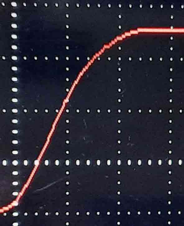 One column in x is about 2ns means maybe the rise time is about 4ns? so: 21cm/ns * (1/6*4)ns ≈ 14cm Even with a rise time of 2ns -> 7cm it would be ok. I think the lines from the FPGA to the HDMI chip will not be >7cm. This is cool. This will reduce the space needed alot. Sure I could have used 0402 resistors and no resistor netzworks but this is a pain in the ass to build up. |
| 09.10.2023 new Project, vacation, ultraDev+ |
Hmm... ok already quite some time passed by... Well at the end of july a new project catched all my focus. Really fun work on
this... But in the middle of august I recognised my batteries are empty and I'm pretty much leeched out. This resulted in nearly
doing nothing for weeks ok to had to work bla just waiting for my vacation. But ! at the end of september my vacation started. Yeah that was good. I have been in denmark for some time and today is my first working day... I'll try to share my time a bit between ultraDev+ and the new project. Ok tbh I'm not very good in this ;) Usually I'm not very good in this. Usually I only can focus on one project and this lasts mostly 3 or 4 monthes and then I need a project switch. Mostly because something different catched my focus ;) But sometimes it's good to have longer breaks. This gives you a different point of view when you change your focus again to the project. Same for ultraDev+. When I started to work again on it mh I asked myself. Why I do not use HDMI? When I started to layout the PCB for it I had longer thoughts about changing to hdmi. 2 things have been against to use it: a) I do not have enough pins. But the HDMI controller I use has a 12 bit mode which needs for the data transfer 12 pins instead of 24. Which I forget. b) I do not have enought memory. To init the HDMI controller I need one block ram which do not have. But now I'm using a 6502 which could init the controller. Hm another thing is. Why I do not have a sd card adapter on board? That could provide a volume on atari with read and write support by default. Without the need of a folder share server running. No question (at least for me folder share is an essential thing) I'll not skip this but having a volume on sd card would be nice. For a sd card I do not need alot new pins on the FPGA. I mean for the boot rom I uses SPI and SPI you can use with sd cards too. So after the break it was clear. I'll do a new revision of the base board of ultraDev+. Well I have some kind of perfectionism. I have to change this.:) And on the other hand it makes no sense to introduce that stuff in a later revision when it's already released and delivered. It makes more sense to introduce this now. Even if it is alot of work esp. routing the HDMI stuff. I have quite alot tracks on very little space. But looks good I think. Most of th tracks are already routed. Changing to a 4 layer PCB is no option. So now I'm really at the max capatilities of the PCB manufacturer. 0.127 tracks and 0.127 space between tracks. Or vias 0.2mm and 0.5 in all. This is awesome. Ok for for 4 layer PCB which I used in ultraBoost it's even smaller... anyway very impressive... So to make a long story short. I'm working a new revision of ultraDev+. I think this is a good step into the right direction. |
| 14.07.2023 ultraDev 6502 CPU |
Unforunately not much time in the last days. But it's working pretty good. The new FPGA 6502 firmware for ultraDev is growing. Uploading of a prg works now. And puh it's not slower than the pure FPGA implementation. Well Since the 6502 is a CPU it of course does not reach the rate of flow like a 100% FPGA implementation. It seems the limiting factor is the Atari. Yeah I guessed this already also you have to take into account the data is read from the cartridge port which slows down the access. I think hm didn't measured this yet I'll do the next days... So far Uploading of a prg, 6502 firmware, 68000k firmware is working. Currently I'm working on the volume share. If course it's a bit of work but the flexibility is awesome also it's absolutly fun to work on this. It's like creating a computer in hardware. This must have been the same feeling when the creators of the Atari or Amige have been working on the computers. Sure it's more challenging doing this is real hardware I ment more what do we need? How can we do it with the stuff we have? Or do we need another chip? For example I recognised it would be really nice to a have some kind of timer in the 6502 maybe to create a task which should executed in an interval like a blinking led or a time out. So I'll just include some kind of a timers maybe 3 or so which can create irqs. That's fun the flexibility of FPGA is so brainblasting. Normally I planned to do more CPU based hardware things. But somehow FPGA I can't stop working with them... Also with ultraDev have the perfect application example how to use the FPGA. Often ppl do not know what to do with the FPGA because they do not have an application what to use it for. Theoretically you could add new FPGA commands for this I'll add to the ultraDev.exe the possibility to send custom commands. What the command does you can decide in the 6502 firmware of the FPGA. Also I'll add a possibility to upload/execute 6502 code from the Atari. Means you would have a second CPU running with 50mhz. Very like the host interface to the Dsp on Falcon. Of course a 6502 will "never" reach the speed of the DSP even with a fast 6502. But an advantage is of course the host interface would be only needed to transfer the 6502 code. Accessing a calculated result of the 6502 could be done directly in the cartridge space since the 68k has direct access to the 6502 space. I like the idea ;) Sure most of the ppl will not use this... |
| 07.07.2023 ultraDev 6502 CPU |
Oh man. The last week have been really terrible. Basically the 6502 memory Interface worked
but by adding more features to the interface it ran into more and more problems. Also multiple writes from the 6502 core have been a problem. Well normally I do almost 100% synchronous code almost everything I did is synchronous logic. For the memory I had to use combinational logic. Of course some standard things you need to use combinational logic like creating a port on the fpga which can be an input or output like the ram data ports. But... What is the difference between synchronous logic and combinational logic? Synchronous logic is synchronous to the clock means the values can change only when clock changes (posedge or negedge). Also changes from the inputs are only recognised when the clock appears. Combinational logic the inputs are evaluated "immediately" same for the outputs. Means the reaction time is alot faster then the synchronous logic... Of course you can do most of the stuff with synchronous logic. In case of the memory interface it was no option to use synchronous logic. When the 6502 for example reads from memory it gives the address to read from and expects the result on the next cycle. When you use synchronous logic here you will have a delay till you have a result because the synchronous logic will see the read too late and when the 6502 excepts the read data is not available. Anyway but realising this needed a few recoding of the memory interface since I never did this until now. And showed my ignorance for this topic. It was a real pain in the ass to do this tbh but I learnt alot. Also showed that the Xilinx tools esp. the simulator is an absoulte piece of shit. I was working the entire week with that thing and had 100 or 150 crashes? Holy shit that was so annyoing... Was not easy to manage this. Quite a few times I switched off the computer and thought fuck you Xilinx. Anyway it's working now I really hope it stays like this. |
| 30.06.2023 ultraDev 6502 CPU |
Uploading of the 6502 works now. Wow what a development time improvment...Just assemble and I can change the behavior of the FPGA.
Now I'm working on some standard routines printf style text printing with hex values in a string for debugging.
Also I started to code the upload for prg files but not finished yet. It was more important to have some nice debugging basic routines. A real journey I had with the assembler this week. As I wrote before I've decided for acme. But somehow this assembler is really retarded. Macros are a pain in the ass and I was not able to do what I wanted to do. Guess ;) Yeah I kicked acme now and tried Kick assembler again...Changed almost the entire sources to Kick assembler and I don't know like it. So I skipped Kick assembler again. And in the end I'm now using dasm again. Somehow I like this one most. And besides there is a nice vscode extension with some more advanced features for dasm...Nice.. Somehow it feels like comming home...;) |
| 24.06.2023 ultraDev 6502 CPU |
That made my day ;):
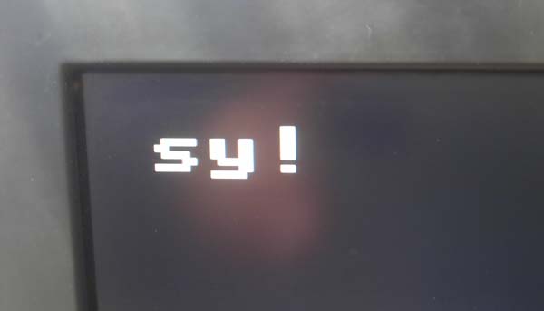
This is the first working USB communication with the 6502 core. Yeah as you can see the 6502 can write to the screen too. That's very nice for debugging. The communication between host and FPGA is command based means SY is the sync word directly followed by the command id. Since the debug screen the font starts ascii code $20 S becomes an s and Y becomes y.! is the command id means 1...1 is a Get FPGA version. The 6502 code for the answer looks like this: cmdGetVersion: lda #$12 +USBWrite lda #$34 +USBWrite rts And the version $1234 I get in the ultraDev.exe. Puh that's pretty cool. It's so easy now to add new commands to the FPGA behavoir. Normally you need to define states in the FPGA state machine, do the code, test that's so much faster to develop... Basically I have all I need to code the first more complex commands. Of course upload of the 6502 code is the first I'll do. Nice! |
| 20.06.2023 ultraDev 6502 CPU |
Ui it quite "hot" in the last day here in Germany. I'm happy I isulated my roof and walls so it's not getting too hot here in my working room. But still too hot somehow to do accessive coding But still today we have around 30°C I really hope it's getting better soon... In the last day I continued working on the 6502 and FPGA memory interface. Coded a new USB communication module for sending and reading a byte over the FT245 chip. And well after finishing it was time to select a 6502 assembler. Hm after asking axis which should I use? Well seems there are several assemblers out there which are used. Hm I tried out kick assembler some time ago so far I remember somehow I didn't like it. Dunno what is was. Of course I used 6502 assemblers before. The OMD (VC-20 demo) or No Pets Allowed (Pet 4032) have been done with dasm. But I think dasm is not really standard. So to make a long decision story short... I decided to use acme. So after starting the 6502 code for ultraDev I had to change the entire project and top source. Ui quite a bit of changes. And what do you do I you try out something new? mh? Yeah let some leds blink. (You can see at the lower side). I know doing a video with blinking leds is well not very impressive... But this was a small success... Somehow I love linking leds. That must be something from my childhood or so dunno. My partens always had a good present if the it had some blinking leds in any way...hm anyway;) So the 6502 CPU inside ultraDev is working. That's pretty cool... But somehow I wasn't able let the 6502 CPU run at 100MHZ hm somehow the logic is too slow. It seems I had a misread when I selected the 6502 CPU core. It runs at 100MHZ on a Spartan 6 I'm using a Spartan 3 Hm running at 50Mhz seems to work. I think 50mhz is still fast enough. Sounds not like a problem to use 50mhz. But different clock domains inside a FPGA is more work. I mean using memory or writing to flipflops from one clock is easier. Really hope this will not be a problem did do this too often. But it's more work to get this working. So currently I have 50MHZ, 100MHZ and 108MHZ but there will me at least one more. So it really exciting currently. I think I really can start soon with the basic stuff like uploading a prg. But really alot of work since I have to recode most of the FPGA code in 6502. But for sure this will be alot faster (coding time). Tbh I didn't expect the led blinking would work on the first try. Simulating your stuff rules and saves time ;) Coding on FPGA is as I said quite often quite different. On a CPU you do not have to fight with all these stuff. So really the next what I need to get to work is to make it possible to update the 6502 code from PC. If this is working it will be awesome. I do not need to create the FPGA programming files each time. I just can assemble and upload. This is a question of seconds instead of 3/4 minutes and even more if you simulate the stuff before... Just Awesome! ;) |
| 17.06.2023 Kieler Week Bus interface 6502 CPU Website hack |
Yesterday the world biggest sailing even started in my home town. The Kieler week. Really alot ppl are comming over during the week and the entire city is
full of ppl. Usually it's not downtown is more or less dead inside the week. So finally something up here.
 Kieler week is so far I remember 10 days long.
With over 20 stages in the entire city with free concerts it became a mega party even in the last 20/30 years.
Kieler week is so far I remember 10 days long.
With over 20 stages in the entire city with free concerts it became a mega party even in the last 20/30 years.That's really fun I've have been there yesterday and well I had the impression yesterday that people have to catch up on something after the corona years. unbelievable many ppl have been there.  Even some bigger bands are comming to the Kieler week. So I guess that will leech some time the next week. Stupidly, I'm not on vacation... anyway
 The week ends with the traditional firework.
The atmosphere is absolutely awesome. And everyone is sad the week is over. Ok some of them are certainly happy it's over ;) Because going to the Kieler week every day and then to the clubs until the morning is really exhausting. I did that 20 years ago but well I'm too old for that...;) Tbh I have been a bit lazy to update the site but I haven't been lazy ;) During my vacation I finished the bus interface but mh 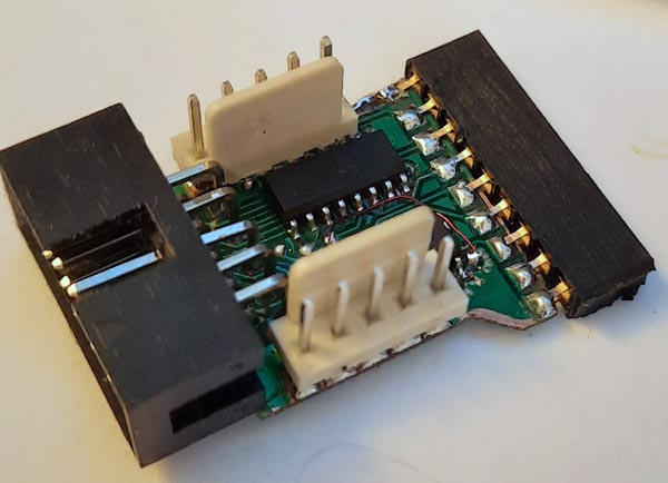 Somehow I'm not satisfied it's fiddly to build. And the bus interface is difficult to unplug. I think I' redesign the PCB again (that is already the 3. version then)
But I think this is better...
Somehow I'm not satisfied it's fiddly to build. And the bus interface is difficult to unplug. I think I' redesign the PCB again (that is already the 3. version then)
But I think this is better...Currently I started to refactor the entire FPGA firmware. Well as I mentioned earlier I'm planning to add a 6502 CPU to do the entire USB communication between FPGA and host computer. That will be a bit of work but it's worth to do this. This also gives others to change the FPGA behavior a bit. Sure the interface to ST will not be done with that. The 6502 CPU will also have access to the debug screen which will increase the development time alot. I mean changing something in the FPGA code costs round about 3 minutes to implement the design to a file which I can upload to the FPGA. For more complex things you usually need to code test to simulate the new feature. FPGAs are parallel processing and it's not always so easy to code new stuff without tests. Currently I'm working of the bus interface between the FPGA and the 6502. Luckily the everything fits into the memory of the 6502: $0000-$0200 Mirrowed from $e000 $1000-$2000 Hardware registers $1000-$3000 Debug screen $4000-$7fff 68k firmware memory $8000-$bfff Data memory (hd buffer or send data to atari) $e000-$e0ff Zero page mirror $e100-$e200 Stack mirror $e200-$e290 Jump table to communication routines and usb routines -$ffff 6502 fpga firmware memory As you can see the 6502 has access to the 68k code/data and as mentioned before to the debug screen. Of course it's possile to upload the 6502 code during run time. This is really what I love about FPGAs its flexibility you can create interfaces or if you need a different screen output format on vga for example you just do it. It's really comparable with Lego. I loved Lego back in my childhold because of its flexibility. So mainly I'm doing some test fixures to test the interface. But currently no implement for the FPGA I did. I really hope the interface and 6502 is fast enough to run at 100mhz. But creating the 6502 firmware later will be surely alot of fun. Really cool is its flexibility. Finally my www.ultrafex.de site is back. Have been hacked and I remove the inserted code. Seems it was originally planned to grab credit card infos from back accounts. I still don't know how they did this. Anyway changed all passwords now I hope it's not happening again... |
| 03.06.2023 Vacation ultraDev+ STE FPGA code Website hack |
My vacation was pretty nice and relaxing. This time we have been in the south of Germany. Well Usually we travel a bit further
for vacation. But I have so save a bit of money for the house... anyway But south of Germany is nice.  As you can see quite some mountains. We biked alot but well this day we go there by using a cable car. We had to go to the cable car station
up to 400m and this was already quite exhausting. I'm too old for that ;)
As you can see quite some mountains. We biked alot but well this day we go there by using a cable car. We had to go to the cable car station
up to 400m and this was already quite exhausting. I'm too old for that ;)We had 2 weeks of sunshine friendly ppl and well food in the south is nice too. Of course alot of time during biking to think about the future of ultraDev and where I want to go with ultraDev+? Our travel we did by train. So I had alot of time to read stuff... So what to read? 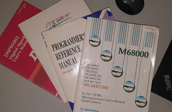 Yeah excatly... finnally I read the User's Manual for the 68000. Really interesting reading esp. when you are about to do some 68k
memory stuff.
Yeah excatly... finnally I read the User's Manual for the 68000. Really interesting reading esp. when you are about to do some 68k
memory stuff.Hm as I mentioned earlier I should have read that before I started to develop ultraDev+ but luckily reading it had not direct consequences to the hardware design I did for ultraDev+. Also I finally know how the Atari or better the MFP generates its interrupts. I mean when I coded on Amiga and ST I knew the 68000 has 7 interrupt levels which are initiated with the 3 pins IPL0-2. The Amiga and Atari has its well known auto vectors starting at $64 for each level. But how does this works for MFP irqs? I mean requesting a normal irq you just pull down the IPL lines and the 68k starts an irq. But all the MFP irq are starting at $100 the user irqs. How does this work? This depends on if the avec (auto vector) signal is pulled down or not. If pulled down the 68k uses the auto vector vectors for the irq. If not pulled down the 68k initiates an irq acknowledge sequence and waiting for the vector which should be called from the user irqs. The initiator gives during an irq acknowledge the number of the vector on the bus. Interesting. I didn't know. Doing this here is mostly investigation since I'm not very into 68k hardware. But interesting for sure! As you can see quite some other books for the 680x0 and DSP. When I started again to code on Atari back in 1999 I ordered these book from Motorola for free. For free from US that was quite cool. Mainly I was interested in the 68000/68030 Programmer's reference. Why not to order the other 68k related stuff...TBH I never thought I would have a closer look in 1999 to the User's Manual since it's hardware related only. Good that I ordered it... Just 24 years later I read it fully ;) That Motorola service was nice. Later I ordered some samples for DSPs: 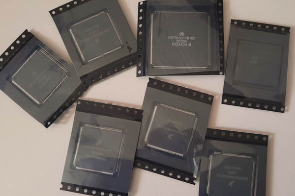 Not sure if NXP still offers this service... anyway During biking had alot of thoughts about if the planned lines for the bus interface is really enough. Is it enought to create all what I want do it? My orignally planned interface has 10 lines. Hm... Did I ever mention I have some kind of perfectionism? So the answer is clearly no. 10 Lines aren't enough. Originally planned all addresslines and the read and write signal. After a long process I decided to change the bus interface means I'll still use 10 lines which go inside but I'll add a small pcb inside of the STE to grab more signals. Today I started to create the PCB. That's the small pcb: 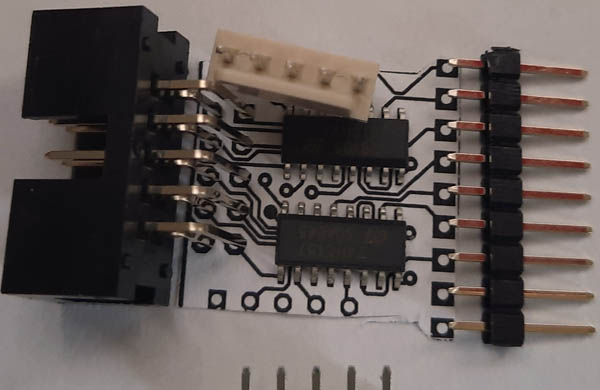 It still receives the 10 lines from the ultraDev+ PCB but by using a multiplexer I can grab 16 signals from the STE. Yeah alot more. But still not perfect. Basically it would be possible to access the memory from the STE by DMA. Means it would be possible to debug directly on pc the memory content. Even if I would have loved to included that I decided it's too much work. The gain what you get is too less... Really hard to decide this. Would be cool but I guess no one needs... That would have mean to recreate the Atari 16bit interface by using a CPLD (small FPGA brother) But is it really needed? No. That was a hard decision but it's not worth the work. The small PCB where I planned to add it. Also I need to consider it must be a) as easy as possible to build up b) as easy as possible to install. 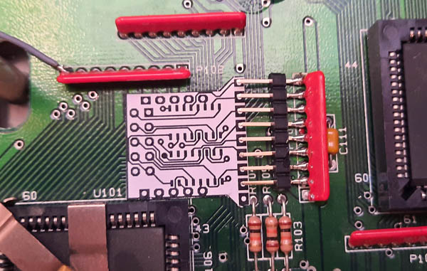 Space is a bit limited but hopefully that will fit. With this interface I'll be able to grab following signals: a23-16 dtack address strobe 8mhz clock display enable horizontal sync vertical sync read/write signal Thats already pretty much what you can do with these signals... So after the planning for the bus interface was completed, I thought about how to proceed with the FPGA firmware. Well that was my first bigger FPGA code and with a view to supporting even more platforms. What does that mean? Is the current good design enough to do that? Is it flexible enough? I do not think so... The code is oki and I'm fine with it. The entire communication between the host computer and FPGA is done in logic means it's pure FPGA code. To gain the maximum flexibility it would be wise to let the communication do a CPU included in the FPGA. So on the way back to Kiel I investigated a bit how to do that and what should I use? In the end I decided to use a 6502 CPU. I found an implementation for Spartan 3 which can run at 100mhz. Niceness... 6502 is perfect for me since I already coded alot stuff on it... Also it would increase the productivity since I can code the bus communication in 6502 code. This is alot more flexible and implementation time is alot faster. I mean changing the FPGA code means about 2 or 3 minutes to wait until the FPGA code is implemented in a file with which I can programm the FPGA. But changing to a CPU for the commuication is quite a bit of work. it's a bit like ripping out the heart and replacing it with another one... Up next is to create the PCB for the bus interface... I'll do tomorrow let's see if I can handle this. The traces and spaces for the PCB are a bit beyond my possibilities here at home... Pushing the limits ;) Don't want to want 10 days to get manufactured PCB...Stay tuned And last but not least in my vacation a mail from my web hoster arrived. They said my webpage www.ultrafex.de have been hacked and they placed some stuff inside the sub directories. They are right. Indeed. Hm dunno how they did that I'm not using any wordpress/drupal/mysql stuff on my www.ultrafex.de page. It's just a link page. Also my FTP password is strong. Odd... |
| 18.05.2023 ultraDev+ STE |
Last days have been a bit stressy... Well tomorrow my vacation starts and going to Freiburg in Germany. I was working a bit on my house
(solar system at the roof) and work took quite some time. But I had some time to continue the tests for the new ultraDev+ hardware. The improved VGA stuff and ram is working. So basically everything works as planned. The thing I struggled the most was getting the ram to work. My milestone before my vacation was I want to write from the 68k directly to the new memory on FPGA in full speed. That works now ... hurray. But the way to it was a real nightmare. I had so many problems to get this to work like I connected the extended bus interface to the wrong places in STE, in my FPGA project uds and lds was exchanged, bad soldering point and mh the most time I struggled with the STE bus timing. Well too much self-confidence is not good. I mean well no problem I know how the 68000 bus interface works DTack UDS LDS kids stuff ;) But it wasn't. Basically it's no problem when you read how the bus interface works. I thought it's working like a normal static ram interface. Of course its not working like this. Reading the 68000 Users Manual could have saved some time ;) aaaaanyway The result counts. I'm now able to write directly to the FPGA memory in full speed. It's kind of mirrowing part of the STE memory to the FPGA memory. Ok not perfect yet only byte accesses are working but that's already most of the deal... So better stop talking I still have to pack my suitcase...cya |
| 09.05.2023 ultraDev+ STE |
Today a tested a new hardware feature of ultraDev+ which is currently for STE only. I'm talking about the extended bus Interface. This is how it looks like: 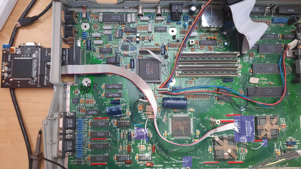 As you can see not too hard to install... The new Atari cartridge connector has an additional connector to grab more internal signals. When you plug in the cartridge you also plug the small connector to the PCB. Of course this is not always needed only for some special features: 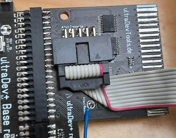 The connector holds the address lines from a16-a23, rw and reset line. Clock signal is not included. I have to do some tests to see if the clock signal can be grabbed without problems. But seems to work so far. I was able to let one of the leds blink on the cartridge by writing something to the $FF8240 register. This is pretty awesome... Next is to test the ram and its interface... |
| 08.05.2023 ultraDev+ PCB |
Oh man. On friday I've got a mail from DHL your package will be delivered today. I thought yay this can be only my ultraDev+ PCBs !... Rest of the day I tracked the tracker by updating it every 5 minutes or so. ;) I want these PCB now! Shortly after lunch time suddenly the tracking disappeared just 2 stops before my house. Nothing happened for the next 4 hours. In the end it seems something happened during the tour and it was shifted to the next day. This was really mean. On the next day I finally got my package. This was included:  If you look closer you will see the first bug. The text is too long (cartridge the e is missing) oh noes... anywaaay... 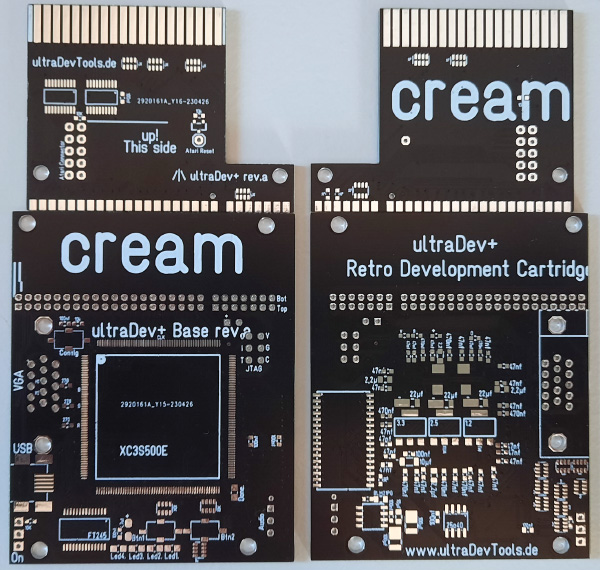 Finally the new PCBs arrived. But I have to say this was quite fast I mean I ordered the PCB on 25.05 and they have been in my home town on 05.05. Not bad. And schnipp: 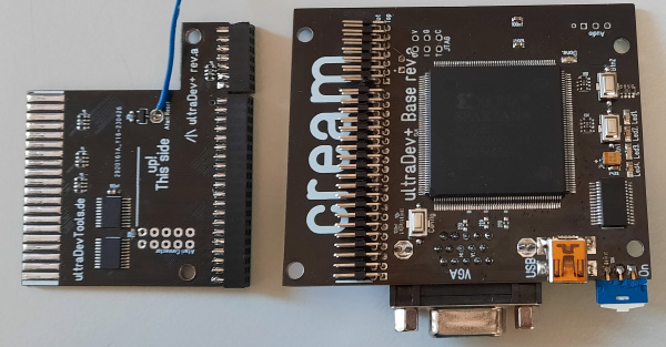 First fully build up ultraDev+ cartridge. As you can see the connector to the Atari ST can be changed. This means it is possible to create connectors for other systems. Or for example would be possible to create different connectors for Atari. One maybe for development, one with a sd-card holder to create something like Ultra Satan or maybe a floppy emulator. The strength of ultraDev+ is its flexibility... The new hardware features are quite powerful. I tried to look a little into the future and tried to develop the hardware with a view to the new features that might come. That was quite a bit exhausting, however, because developing hardware for something that doesn't exist yet or it's not yet clear what features might come. I changed the hardware several times and I mostly opted for the maximum solution. Interestingly I had a lot of new ideas for the Atari version of ultraDev+ during this time. It was exhausting but it was worth it I think. Build up itselt worked quite well. But the first build up needs always a bit more time. The PCBs looks quite alike the old version but there have been changed quite a bit. Also pins have changed. The first test of the cartridge of course did not work very well... That means tracing down bugs or mistakes. Well if you build up something for the first time you never know is it a problem of the hardware design, software/fpga code changes to make the new revision work or is it a problem because of a bad soldering joint? My goal was to have one firmware which works on the last revision f and the new ultraDev+. Luckily I was able to do this. I added some resistors to the PCB to identify if it is a ultraDev+ or not. State now is ultraDev+ works as good as the last rev. f which is quite good. So far now mega big hardware mistakes. The only shocking mistake was as soon as I connect a monitor the ultraDev+ and the Atari did not boot up anymore. Uff I already thought fuck did I blow up my Atari? After a checking the schematics again I unforunately saw I used the INIT_B pin from the FPGA during boot up it is not a good idea to pull this pin down. Connecting a VGA monitor did this. Workaround is just to connect a monitor after switch on anyway no big deal to change this. So up next is to test the new features of ultraDev+. I hope I'll not discover more heavy hardware bugs but until this point I'm quite happy it's working so far. Here again a compare ultraDev+ with rev.f: 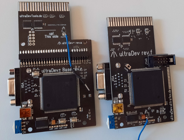 |
| 05.05.2023 ultraDev+ PCB |
Looks good so far. I have soon almost everything I need to build up the first ultraDev+ PCB. The PCBs are already nearby my home town. I guess I'll get them today... In the last days I was fighting a bit with cutting plotter to create my stencils. I use the stencils to print the solderpaste to the PCB. Hm do you know this? Everything worked fine last time. Next time you want to use it. It doesn't work. Meh. I have a cameo 2 cutting plotter to print out the stencils I use gerber2graphtech. A small too which can convert the PCB layout into cutting commands. Works not too bad. If it works. But the solution is a bit hacky like creating a link from the printer and then the tool outputs directly to this link. Unforunately the link I created 4 years ago changed its destination and it went from USB00x to LP1. Cool how can this happen? I mean I did not change this. Anyway that took quite a while to figure this out. I mean error while printing from Windows did not help here really. |
| 29.04.2023 ultraDev+ PCB ultraDev Fixes Interface Kiel |
Yay seems my PCBs for ultraDev+ are done and they have been already shipped... Cool. I have been working a bit on the prg-file start code on PC. I made it a bit more "intelligent" like recognising it's not a valid prg-file. It also handles can handle segments on odd adresses or stripping symbols from a file. I saw I always generate the Bugaboo prg-file with debug symbols.So each time you start the debugger round about 50 kb are transfered for nothing. Eh Ops ;) In future symbols are only transfered to the Atari when they needed. There is a small retro meeting today. Interface Kiel. Its not really a scene event but seems some scene ppl are comming over from oxyron or onslaught I'll check out never have been there if it is boring I'll go home and work on my stuff... Besides since I do not have a car (oging by bike) a good trip to get back my old fitness level ;) |
| 27.04.2023 ultraDev ultraDev+ PCB |
Seems all ppl who bought ultraDev are asm coders or not using the cartridge to code... I thought ultraDev can start everything until Matt came along with his small hello world prg ;) The file is generated by gcc vincent toolchain... which just don't work... Back in 2019 when I started the ultraDev project was not very into system coding (not that I am now anyway) one bigger thing I needed of course was to start a prg-file. Starting a prg file from disk or hd is no problem just use pexec. But how can I do it with an environment which can't load from disk or hd? Well no problem I thought... I have a relocation routine just load it and relocate and execute ... And done! ... Yeah... Hmmm not really and it turned into a real pain in the ass. I recognised more and more programms I can't start prg-files because they need the base page (something in for a process in Tos) so I started to build up a base page by my own. Hm unforunately it turned out in a real night mare... And of course with Matt's small hello world prg I had again a problem with the base page. I could fix that but it still not working fully. The file has debug symbols and seems gcc creates symbols with a odd length which results in a odd position for the relocation table -> address error ;) Ok fixed too Still don't work 100%... Bla. Oh man. And after 2 two years I think this was really a bad decision to create the base page by my own. But typical problem something which looks easy at the first glance mutated into something really complex. When do you pull the ripcord? Just a little more and then it works but this time really ;) Ok nice side effect is you learn alot. You get deeper into things but this need alot of time. Another problem I know of a PTerm of a prg results in a crash in ultraDev. Yeah no big problem normally but I really started to fix that problem by hitchhiking the trap and intercept PTerm to exit clean (but stopped that shorty after I started. unforunately some effects of my need for perfection...) You see my point? Just a little and it works ... really... ;) So today finally pulled ripcord and started to investigate how you can start a prg from ram legally with the system. I was browsing alot system sources and of course I read again the Tos reset handler and boot process. I did this in 2019 already which is the best point to execute the cartridge code. Luckily I found that position right before the execution of the auto folder... But why did I stop to read after that point? Well why didn't I read some more maybe 10-20 assembly lines more of the reset and boot process routine? Man that could have saved me days/weeks of work. What I'm talking about is when Tos is resetting it trys to boot from floppy/hd and what it does then? Yeah it enters the desktop. The desktop is started as a process excatly that what I need. Both things I needed that close to each other and I didn't find/see the second... That's life... Oki need to do an example how to start an incbin prg-file to see if this works and then change the entire prg-start code for ultraDev prg-files that will be fun. Wat mutt dat mutt... Like we say in north german jargon means "What has to be done, has to be done"... Something is almost done are my ultraDev+ PCB... They are surely done next week so maybe I can build up the first ultraDev+ before my vacation... That would be awesome... |
| 25.04.2023 ultraDev+ Atari 16bit |
The new PCB layouts for ultraDev+ are done and I gave them to the PCB manufacturer. Looks like this: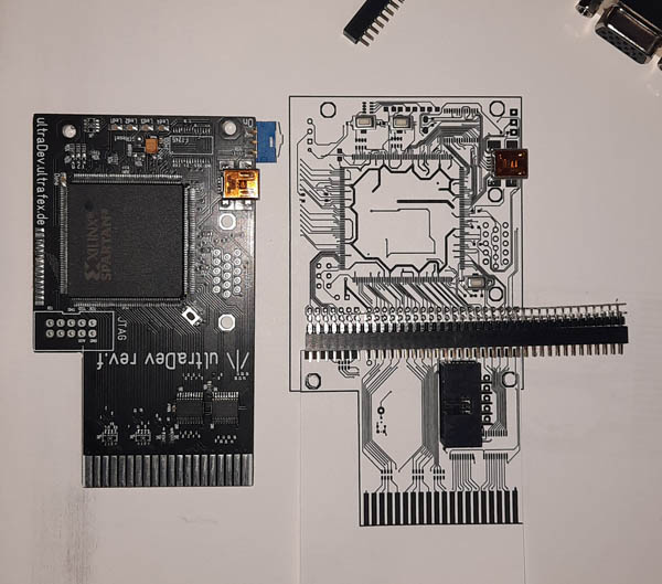 As you can see the ultraDev+ PCB is slightly bigger than the last f revision. Mainly because of the connector and the new ram. On the lower connector to the Atari you can see the new connector for the additional adresslines. It's a 10 line cable can be soldered quite easily to the Atari. This is not needed for normal usage of the cartridge. This is more for future features I'm planning. Puh I'm happy the PCBs are done. Hopefully I included not too many bugs but we'll see in about mh 14 days or so. |
| 24.04.2023 ultraDev+ Atari 16bit Domain |
That idea with the second screen is huge but it makes only sense on STE. On normal ST I'll not try this. Some days ago I thought again how to speed up the screen transfer to FPGA memory (wrote earlier about that). Last idea was to sniff the bus and grab the reads from the movem (138 rasterlines that would need). Hmmm... Hmmm... I mean when I sniff the bus why should I transfer the entire screen to the FPGA? Why not grab the writes to the screen area? That would need no extra code and will be full speed. ... BOOM. What a cool idea! I could even create higher resolutions on the VGA screen. That is something I really have to try out. So in the last day I focused to finishing the FPGA base board and the Atari ST connector board. The ST connector I extended a bit and added the possibility to connect a small cable (10 lines). These lines are soldered to the STE to grab the rest of the address lines. To recognise the writes to a specific memory I need to clearly recognise the write addresses that works of course only with all address lines. The idea I had before with grabbing the reads from the movem would have worked with the cartridge ports address lines because I'm grabbing the data in a well defined time intervall. Writing to the screen memory can happen everytime so a 100% identification is inevitable. So the cable has A16-A23 (the ST full address range), 68k read/write signal. This Helps to sniff ;) Ah and also the reset line (no need to connect the reset cable anymore then). I think I'm almost done I hope I can send the layouts today or tomorrow to the PCB manufacuterer. I decided to shift the implementation of ultraDev+ for c64. I really have some more ideas for the Atari st version I want to try out first... And last but not least the page has now its own domain www.ultradevtools.de ... hurray;) |
| 14.04.2023 ultraDev STE |
Hm there was a sentence in my post yesterday which has kept me thinking the entire day. "Mh would it be possible to add a second screen to Atari ST? I mean a second screen on desktop?" I asked ggn if it would be possible to extend the Atari desktop screen to a second screen. And he said yes there is a tool which resizes the desktop and scrolls the screen or so (did not try yet). Maybe again what is the idea? The idea is ultraDev has a VGA output normally this is used for debug output but why not display extend the atari desktop to it? So I would need 32000 bytes on FPGA to have a output buffer. 32kb I have for 68k Firmware and HD sector buffer. If having a second screen output running it would not be possible to have HD emulation (mh or maybe only with smaller HD sectors currently they are 8kb). And the 68k firmware would not work or maybe only a smaller one. Hm that would work. But how to transfer the second screen to the FPGA memory? That could be a bit slow... The problem is that you can't write to the cartridge port. To write you can a) not set the address where to write directly and b) you are not writing you are reading from a specific address. Small example: lea $fb0000,a0 lea screencontent,a1 move (a1)+,d0 move.b (a0,d0),d0 this writes one word to the FPGA. Each write would need 24 cycles. That will be pretty slow... 160*200/2=16000*24 cycles/512 cylces per rasterline= 750 rasterlines (2,4vbl) heh ok slow... even if you optimise a bit like; move.l #$fb0000,d0 lea screencontent,a1 move (a1)+,d0 move.l d0,a0 move.b (a0),d0 160*200/2=16000*20 cycles/512 cylces per rasterline= 625 rasterlines(a bit over 2 vbl) mh slow... I almost skipped it because of the slowness... But wait a minute sometimes you need to go strange ways esp. when you have a FPGA in background which can do things which wouldn't be possible. I mean I have the 16 bit databus and 128kb address range available to the FPGA What if I do something like this: lea screenContent,a0 bsr setTheFPGAInASpecialMode movem.l (a0)+,d0-d7/a1-a6 /../ bsr disableSpecialMode The special mode activates some kind of address and databus tracing means each read access from the 68k is scanned and automatically written to the FPGA memory. movem.l (a0)+,d0-d7/a1-a6 needs 124 cycles if I'm right and moves 56 bytes. means 160*200/56 = ~572 movems to transfer the screen. 572*124/512 = 138 rasterlines. Maybe it would be possible to do it with the blitter... Yeah sounds like fun have to add this to my idea list... |
| 13.04.2023 ultraDev+ |
Puh finally the new FPGA board for ultraDev is routed. There is one word which descripes this task pretty good...
Annoying... Well the FPGA has 208 pins. To get the FPGA alive you need to feed 44 pins with 3 different power rails(3,3v, 2,5v and 1,2v) and 20 gnd pins. This is a challenge with a 2 layer PCB. Ok luckily I did not have to change this but this already limits the routing for the other signals... To handle this I had to change again track size and distance (0,15mm) again which means I had to rerout and shift alot of tracks... Vias are now 0,5mm diameter with 0,3mm hole. Pretty impressive that they can produce this without problems.. I'm still not at the limits of the PCB manufactor but pretty close... But pretty cool is that I could add ram without any problems. Means I have now 128kb ram with 8 bit size on the board. And the ram is pretty "fast" with 10ns. That's nice so it would be possible to create 128kb ram cartridges for Atari or for example a 640*200 display output on the VGA debug screen (true color.. hehe ok if you want to call 8 colors true color ;) ). Mh would it be possible to add a second screen to Atari ST? I mean a second screen on desktop... Mh2 maybe I really need to improve the VGA output to 256 colors... Hm I think I should add. Usually I choose the max. variation. That's the advantage of software development. Even if your initial design of a software was bad you can change it. If the design of the hardware is bad you a) Can not change it easily. Or better you can but this costs money b) it makes hardware updates and new revisions harder if you want to support the old hardware with the same FPGA core. So better to take yoru time if you aren't used in creating hardware stuff... But now the most annoying part starts. Checking the PCB... Man... This is so annoying... I really hate it. But it's really needed. Well so very easy forget one track let's say a power rail to a ic. Meh. But when it's done the most exciting part starts. Does everything works as you planned? It's so much fun when the first things are getting to work... And if you peek out new features with the current hardware which you initially didn't not plan or you didn't thought of... So... eyes shut and go for it... it's soon done ;) Hm almost soon done. Have to check the c64 connector again before I produce the PCB... But anyway not thinking about that yet ;) |
| 11.04.2023 ultraDev+ c64 version Ai |
First of all some good news. ultraDev will be available soon again and there will be even a price drop. I could order some parts a bit cheaper... Back from 2 weeks of vacations (Hamburg and Föhr (a small german island)). That have been really relaxing... So time to continue a bit... Before my vacation I started to logic analyse the c64 bus. 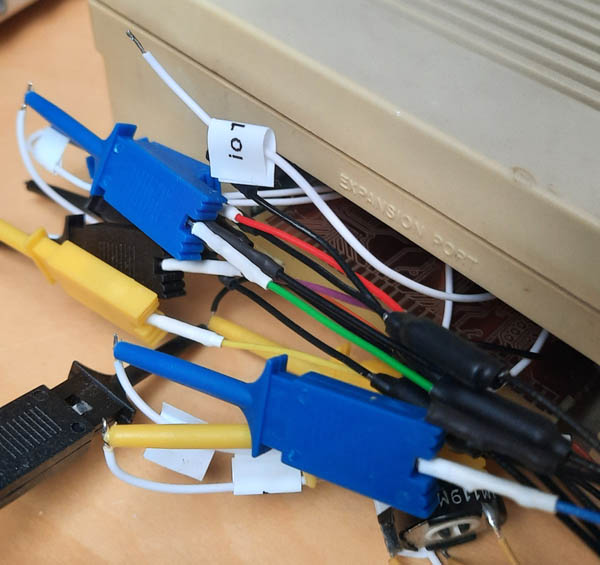 Yeah looks a bit chaotic anyway ;) I could use the PCB with the scratch I created earlier to have a connector to the C64 cartridge port. As logic analyzer I use the the DSLogic Plus: 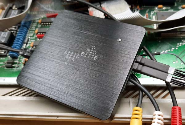 I like that one. it has max. 16 Channels and up to 400mhz sampling (in that speed you only can sample eh I think 4 lines). it supports RLE compression is improoves the max. capture time which is really cool it also can analyse standard protocols. The software is oki so far I read it is a fork of sigrok. it's not too bad somehow it fills my needs. When I bought it it costs about 110€ now it's 133 or so on Ali. I would recommend to buy the plus version instead of the basic. The basic has less memory and can not sample @400mhz. So far I read the 6510 can accesses the memory on the second half of the main clock. One thing surprised me during a write to the memory the write signal goes alot earlier to low than I expected means. Strange is that the time when it goes low also does not fit to the datasheet. Hm anyway have to check that again. I stopped the investigations for a while. Finally the new buttons for the ultraDev+ FPGA board arrived so I can finally finish the new FPGA board. Unforunately that took alot longer than expected and it's still not finished yet. Current state:  Not fully routed yet. As you can see (maybe) it looks a bit different from the old one. At the top I added some connectors so it can have a flexible bus interface to the destination plattform. The holes at the top are to fasten the bus interface pcb with screws. The new bus interface connector has more possible pins which would make it possible to have a floppy emulator for Atari ST by default on board. I'm talking about the HXC USB floppy emulator. Unforunately I can't find a floppy connector for a decent price. Bla this is really annoying... Really I don't know how long I searched the net also on AliExpress for this. Main changes are:
Maybe I should change to HDMi? Would be nice but after checking my ultraBooST PCB design again. HDMi needs by far too much iO ports on the FPGA. Also creating a HDMi output is not trivial. So I'll not change to HDMi. Also thinking about to add more colors to the VGA output. Hm not sure about that. Currenly I will stay on 8 colors. I mean it's a debug output. But you never know I change the decision if I add sram to the new version quite alot. The dac and sram will not be soldered by default. Currently I have no need for it this is just for future features. 2 weeks ago I decided to start a bit with Ai stuff. Means not only use it also how to code neuronal nets and how to train them. Just beause I have a problem at work which could be maybe solved better with Ai also I wanted to know how all these new and fancy features are done like image recognition. I know ChatGPT is out now for quite some time even GPT 4.0. But somehow I really started to use it last week. TBH I always ignored the Ai stuff because I had the feeling it will take some time till it will be useable. I mean look at the google assistent. Well ;) But I was really impressed by how "good" it recognises the speech. To get a bit more into the work Ai problem and develop possible solutions for the problem I started to read how neuronal networks are made and how machine learning is working. Really interesting stuff. Then I had the idea mh everyone is talking about ChatGPT why not talk to it about neuronal networks and how to programm and train them? Does ChatGPT understand my question? is it able to tell me how it works and does it understand my detailed questions? I had the last days quite a few chats over hours with ChatGPT about neuronal networks. And I have to say I'm deeply impressed by the chats of ChatGPT (even from the 3.5 version. 4 I did not try alot). This is really an interesting way of learning something new. I often don't know someone who could explain my questions. So the solution was always a) read a book and maybe your questions is not answered or b) you use google. I don't know how many hours I spent in google to figure out an answer to one question. Sure ChatGPT can't answer all questions. Also you have to be careful quite often the answers are incorrect or are true lies. I mean ask ChatGPT "do you know cream on atari" the answer does have some correct stuff but quite alot is not correct. Bing chat is more accurate but does not talk too much. Maybe it leaves out the stuff which is not correct... Anyway... Still this is absolutly awesome... Mh we are on the verge of a revolution in terms of Ai? I think that will change a lot in the next years. Even if I'm deeply impressed by what Ai is able to do not only chatgpt also midjourney (the ultraBooST title picture is done with it). I also have serious concerns. I think it could be some kind of pandora's box maybe a technical singularity? Heh ok maybe too dramatic ;) But it will cost alot of ppl's job also possibilities for crime is amazing. Mh also I think we need some more rules for Ai. Anyway so better to get into Ai as soons as possible and use the new possibilities. Ai will rise the level of productivity/creativity also for products how to make them smarter. |
| 20.03.2023 ultraDev+ |
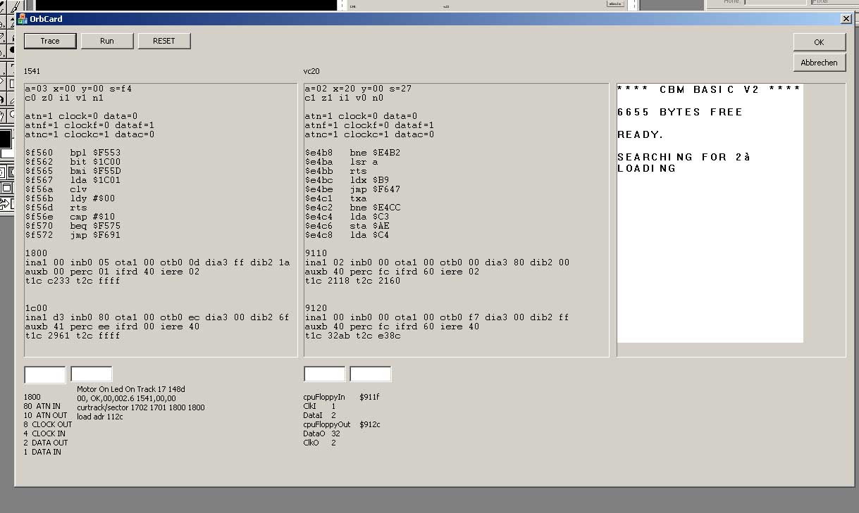
Continued in the last days to build up the c64 ultraDev+ prototype. Ah well 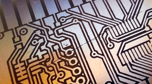 it's very nice if you etched the PCB and then you see there is a scratch over half of the PCB. Cool. That motivates! Anyway so I redid the PCB with the long scratch it makes no sense to continue. Unforunately the acid is in that a bad state that it took about an hour to each the PCB at 45�C. 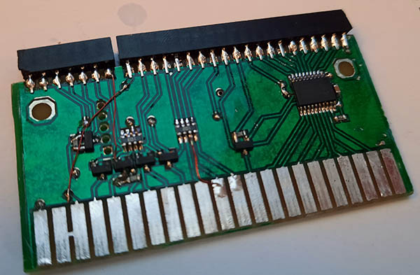 That's the finished build up of the c64 connector prototype. No beauty I know ;) Hopefully it will work fine. The cartridge fits good in the cartridge port. Needs some testing before I connect to the c64. I mean it's the first version so better be careful;) The first version of ultraDev I just forgot the level converters and well 5v on a 3,3v accepting ic is no good... The FPGA commited suicide after that ;) (schnipp ...next day) 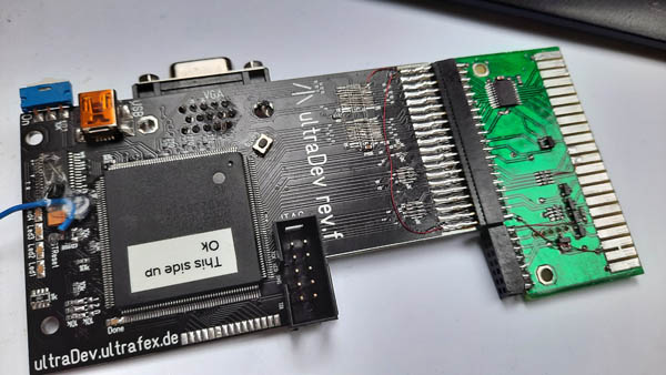 Currently there is no ultraDev+ FPGA PCB available so I had to modify an old one. As you can see (or not) I removed the entire Atari ST interface. The big connector is basically the ST cartridge port that smaller connector on the right has some extra lines and a 4 bit identifier. The 4 bit identifier is to identify the connector type. Each plattform will have its own FPGA firmware. What happens if for example if the FPGA is programmed to use an Atari ST and you change the connector to use it on c64? That could cause in the worst case a hardware malfunction. As soon as the 4 bit identifier does not fit to the programmed FPGA firmware the FPGA goes into a sleep mode. And all connections to the cartridge port are in a tristate. When you execute ultraDev on the host computer it checks the 4 bit identifier and programms automatically the correct firmware if they are different. 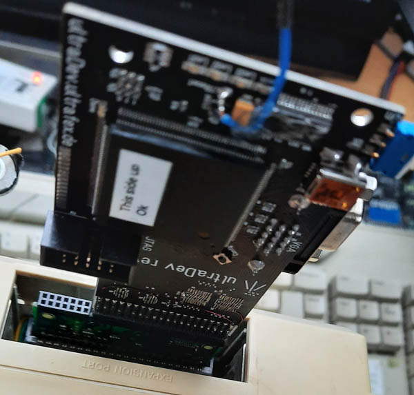 After I checked a bit the prototype. Now I dared to switch on the c64 for the first time (of course FPGA is empty)... And naaa? The c64 starts nicely. So at least I'm not fucking up the c64 bus ;) Next check can I access the FPGA? Yeah I can... Basically I'm ready to start the cartridge. So next will be to setup the FPGA project and implement the bus interface. But... tomorrow I'm going to Hamburg for some days... yay... |
| 15.03.2023 ultraDev+ |
Some weeks ago I sent out the last ultraDev from the last batch. The last batch went pretty well. Except of the Ali Express trouble I mentioned below. Seems I woke up from my deep winter sleep and since some weeks I'm doing stuff on ultraDev again. Can you believe that? ;) Round about 7 monthes I didn't do anything neither ultraDev (except of buildup of course) nor Atari related stuff. But that long break was good. Time to relax, read maybe a book, just do nothing, meet friends, collect ideas and start with sports (lost 13kg of weight). interesting is what made me doing things again... 3 weeks ago I heard/watched a really cool podcast on youtube: "From typewriters to the VC-20: the early history of Commodore" (click) I think the title is self explaining. Unforunately it's german only. I really love these background stories and stuff just awesome. it's a 3 hours pod cast and dunno why this made my doing things again. Since ultraDev on Atari is working pretty good (so far I know ;) ) and mh tbh I don't know what to include next (tin your feature is still on my list;) I did not forget) I'm doing for me the next logical step. Currently I'm working on a multiplatform version ultraDev... so called ultraDev+... I think I talked earlier in the diary about that... My idea is to have one ultraDev base board. For each computer/console I plain to create a connector. You simply change the connector and you can work on other platforms with ultraDev. Out of my investiations/ideas I'm planning following Atari St (not too suprising;)), c64, vc20, c16 c116 plus/4, 2600 VCS, Lynx, Nes and Gameboy... if I really will support all these plattforms let's see ;) But of course I'm open for supporting other ones. So... destination next is?:  Huh? why a Commodore computer not Atari? Well the early Commodore computers have been my sweetheart. I never had an Atari 400/800. I only changed to Atari to ...do things together with the creamies... Hm but why c64? vc20 was my first computer? Well the c64 cartridge port is powerful. it offers more features compared to the vc20. Hm not to mention the Atari ST cartridge port. The c64 cartridge port opens up new worlds my feature list grow alot after I started to investigate the hardware... Just awesome... I know the c64 is pretty much saturated with stuff like 1541 ultimate or other stuff... But something like ultraDev is missing on c64. And tbh I'm not doing this to sell alot this will be a fun project. What I'm planning to do with ultraDev+ looks like this: 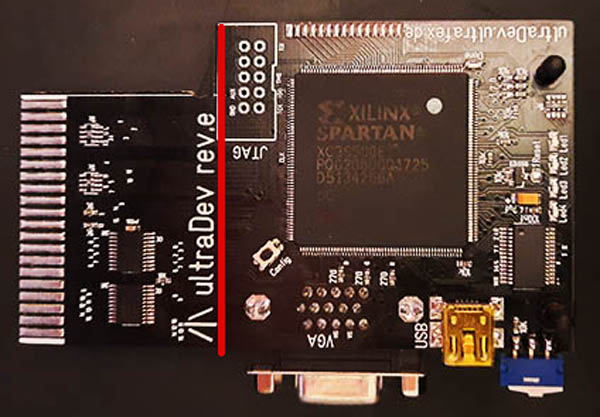 That's the current revision e of ultraDev. As you can see on the right side the FPGA board. On the left side you can see the Atari ST bus interface. The idea is to cut the ultraDev PCB at the red line and add some connectors. So the bus interface on the left can be changed. Another idea was to use the old ultraDev rev. e and the connector to other system has an Atari ST cartridge port. To find this connector is almost impossible. I don't know how many hours I spent on ali express to find such connector. I gave up. But it's I think good like this. I recognised using the Atari ST bus interface would limit the possibilities of new systems/consoles. I mean the Atari does not have a very strong cartridge port it's pretty weak. So having an especially designed bus interface for each system/console will peek the maximum out of each system. First step is of course to design the bus interace for the c64. Never had a closer look to the cartridge port of the c64 in the past. And have to say it's pretty strong one which opens up really nice features. This part of the design process of creating something new I really love alot. Understanding the cartridge port and see what you can do with it and in the end develop features ideas, think about what could be a problem, find a solution, what must the hardware be able to do and in the end layouting the hardware. For the c64 I've decided to support all lines mostly bidirectional. Sure that makes the bus interface more complex but I think it is worth. Looks like this (early stage):  And this time I'll try to do the prototype for the c64 PCB here at home. Yeah I didn't do that since mh 4 or 5 years. Well creating pcbs for the FPGA board at home is surely possible but unbelievable alot of work also the layout must be bigger... But the prototype for the c64 interface is no big problem... So up next is to create the PCB for it: 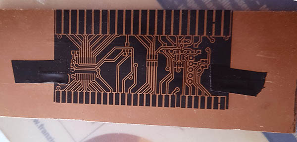 The layout for the PCB is exposed with an uv light. Of course the layout is double sided. Next is to develop the exposed PCB 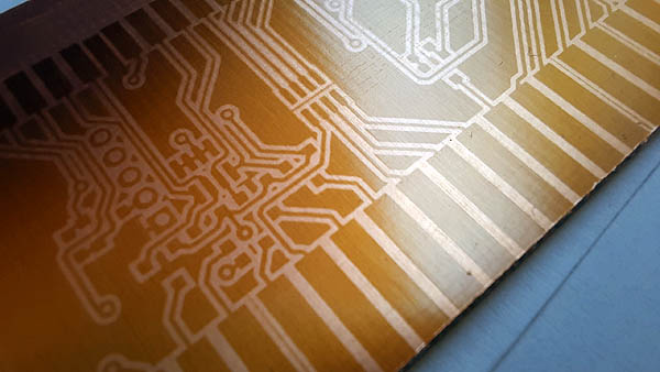 The expose and develop worked pretty well for not doing it 4 or 5 years (sure depends also on the chemicals) the result is awesome... To have a good result here the most important thing is the film to expose PCB with uv light. The printed PCB layout must be opaque as good as possible. Of course you can do this with a laser printer. The upper picture with the layout film is done with a laser printer. No need for an inkjet printer that's nonsense. Use a plastic primer to make a laser printed layout opaque (I'm using Dupli-Color Basic plastic primer...Spay a little and dry it with a hair dryer and repeat 2-3 times). Without that step a printed layout is indeed unusable. With it works perfect I can do 0,15mm structures here at one... Up next is to etch the PCB. Let's see if the Natriumpersulfat (acid to etch the PCB) is good after 4-5 years... |
| 06.01.2023 Ali Express trouble |
Seems I have a run currently with bad stuff... First the Windows update which broke my Xilink iDE now I have trouble with a delivery of USB-Chips. Out of 10 ...3 are not the correct chips and 3 are not working maybe fakes. Really cool. So ultraDev delivery will be delayed... |
| 05.01.2023 FPGA ide trouble |
Some FPGAs arrived some days ago so I started to build up one ultraDev to see if the FPGAs are working fine. After finishing the soldering I wanted to programm the FPGA. But currently I'm not able to programm any FPGA because the ide (Xilinx ise Webpack) does not work anymore. Also making changes it not possible. Seems a Windows update made it not working anymore. So since yesterday I'm trying to reverse eng. with Ghidra and x64dbg man this is so annoying... Well the ide is already over 11 years old but it's the only verision which still supports the Spartan 3. Well I like the Xilinx FPGAs but their software is a real pain in the ass. Hm maybe I need to check if the VM solution for ise Webpack is an option. I planned to start to deliver in january new ultraDevs... anyway I guess I can forget that... |
| 12.12.2022 rl ultraDev |
Not much happened tbh. here ;) I had a longer Atari break after my contribution for the Silly Venture 2022 summer edition. it ranked first in the wild competition. in case you missed it: it is a demo which was created with a video modification developed by me. if you scroll down you can see some of the PCB which I used for the video mod. if you want some more infos about the project you can get them here: Clicky. The ultraBooST project I was working about 3 1/2 years. And since you did not read something here it was a secret project. Everthing you see here like ultraDev and ultraTos was done to realize the ultraBooST project. I wanted to share infos the about the ultraBooST project when it's more or less done. The last 4 monthes I did not switch on my Atari at all... Well the 6 weeks before the party have been really stressy... Also it was really needed to do some improovements to my house like solar system on the roof and to improove the insulation of the house. Luckily I managed to get done before it's getting really cold... And it was worth insulation is not much but helps to keep the house warm. So what I'll work on in 2023? in 2023 I'll work a bit more on ultraDev I think. Currently I'm working on a new revision of it. The idea is to use ultraDev not only as a development system for Atari St/Falcon. My idea of ultraDev is to have one development hardware for the most common plattforms. That was the basic idea of ultraDev ok the basic idea was bound to Atari St computers since this is more or less done I'll start to implement other systems now. Means the connector to the Atari ST is replaced by a pin connector and then you can plugin connectors for the systems like Atari St, C64, VC20, C16, VCS and what ever is needed... The idea is to have one development system for the most common retro computers. For example for c64,vc20 and c16 it would be possible to create a floppy emulator. Of course would be possible to create a floppy emulator for Atari too but really hard to get these floppy connectors :/ I already did 11 years ago one with a pic32 a cycle excat floppy emulator for commodore systems: 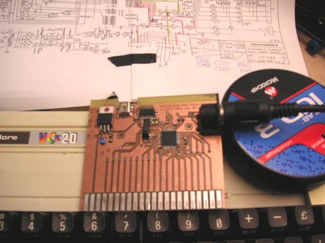
On the right you can see the cartridge which was done for a VC20. On the left you can see a emulation of the floppy and a very basic emulation of a vc20. This was mainly used to get into commodore floppy loading and stuff. The floppy emulator hardware was based on a pic32 with cycle excat emulation of the floppy. Worked quite nice... Of course that would be some work to port that to FPGA but anyway. That's it for now... Ah and I almost forgot. in 2023 ultraDev will be available again. Only a few cartridges I can sell... Half of them are already sold tbh. But I'll devliver after new year 2023... leaving very soon to my traditional to Boltenhagen vacation before xmas . |
| 18.07.2022 ultraDev |
And now it happened... The first broken ultraDev device: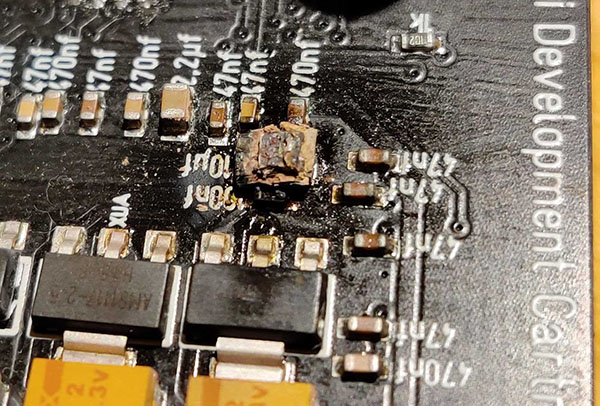 The guy inserted the cartridge upside down. And switched on and wondered why it does not work. Hm so better double check before you insert!. I really hope I can repair it. I'll see if I can do something against it in the new revision. |
| 07.07.2022 Osc repair & mod |
Today I was working on my sds7102v osc. Looks like this: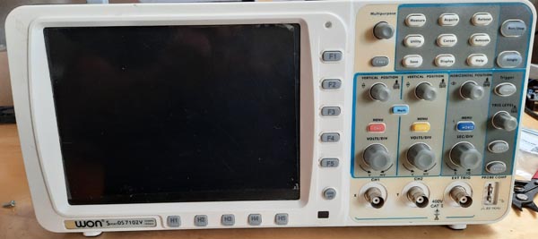 Yes I was one of these morons who bought this oscilloscope. I think if I would have a top 10 of regrets buys this one would be close to #1. Well back in time this was ones cheap and worked so far. But after some weeks I could switch it on anymore. So I sent I back to the seller and it took about 2 monthes to repair. And well I never really liked the osc the rotary encoders do not have an accel which is a pain in the ass to scroll in a sampled area. Second thing which is really annoying is the fan. its so loud unbelievable. Do you know this you switch off something and you are thinking ahh finally silence ;) Some days ago I switched it on and now the rotary encoders are almost unuseable. Great!. Well it's a cheap china thing and often they save parts and try to solve problems with software. So my guess was the debouncing of the rotary encoders is done in software. That works for while but if you don't do it correctly the encoders will start to jump arround and in the end it's unusable. But this is normal for cheap encoders the bouncing increases after some time. So I opened up the osc today and checked if the debounce is done by hardware or software. And it seems it's done by software. The osc PCB with the rotary encoders from the back side: 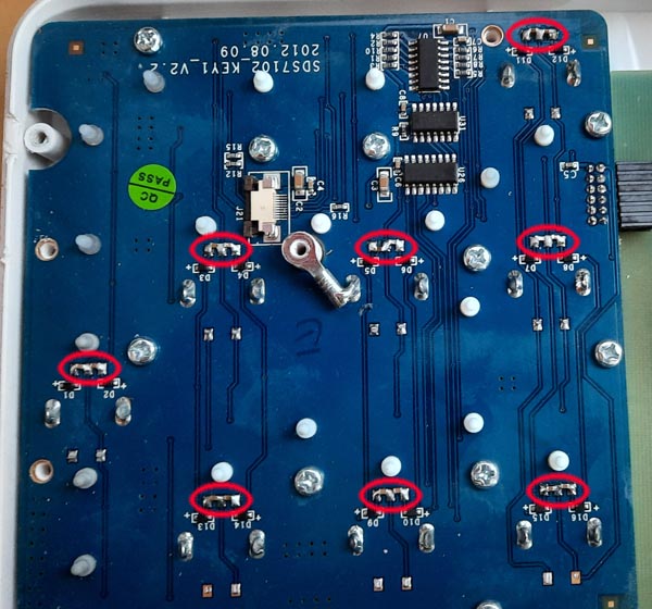 The red circles mark the rotary encoders pins (3 pins for each). What I did now is just so solder two 0603 capacitors (100nf) to each encoder. That's surely not a perfect solution means not every roation speed will work. But it turns out it's working pretty well. Niceness ;) Next is to replace the fan. Replacing it is a bit annoying you have to get apart the entire osc. Fits perfectly: 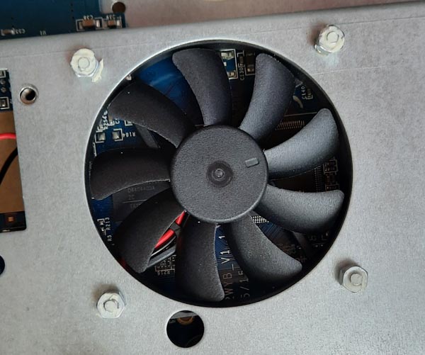 I used MF60101V3-1000U-A99 from sunon for it. The fan is almost not hearable anymore... This is awesome. Hm the traditional left overs after a repair... But seems to work without ;) 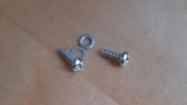 |
| 01.05.2022 Xbox |
Last week I was browsing throu eBay and I found a faulty Xbox one X with no HDMi output. And something said me hm buy me ;)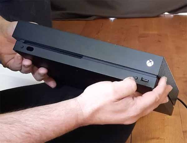 Tataaa... it arrived on friday. it switches on normally as you can see the Xbox-Logo lights up but does no display a picture on tv. Lets see if I can get it back to life. 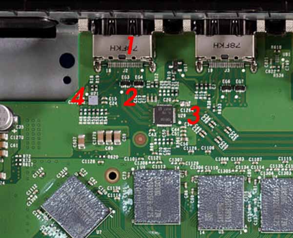 On the upper picture you can see the HDMi circut of the Xbox one x. What can cause a no display on a Xbox one X and how to diagnose it? -A faulty HD. You can recognise that if you switch on the Xbox and if it switches off after 1-2 minutes... my Xbox -> it stayed on so no faulty HD. -On the upper picture 1) That's the HDMi port. inspection from the outside of the HDMi port looked oki. Next is to check if all pins are soldered correctly. Small nudge check on each pin... -> HDMi Port is in mint condition and all pins are soldered correctly. -On the upper picture 2) ESD diodes they protect the internal circut against over voltage. Switch multimeter to continuity mode and check the HDMi lines if there is a continuity for each lines. All is fine here. Next red probe to ground and check the lower HDMi lines of the ESD diodes. Multimeter should display 0,7... All fine here...-> ESD Diodes are fully working. -On the upper picture 3) Thats the retimer chip. it mainly does a level shift of the HDMi signals to TMDS it also can boost the HDMi signals and stuff. Switch multimeter to continuity mode and black probe to ground. Now check each capacitor around the iC of there is a short cut to ground. All is fine no short cut. Next check c50 in resistance mode of multimeter C50 should have around >8kohm. Fine... -> So retimer chip seems to be ok. -On the upper picture 4) ESD Booster iC chip. it does ESD protection for hot plug detect, i2c lines of edid and over voltage protection for 5v. Checking all capacitors around that iC for short cuts. All is fine. Next checking if hot plug detect and i2c lines are 5v when the console is switched on. All is fine. So seems that iC is oki... Hm that's odd all test were successfully nothing seems to be broken. Then I checked the circut again with magnifier glasses. All fine... Hm but the retimer iC (#4 on the pic) seems to be changed by someone. After inspection of all of pins I recognised not all pins have been soldered correctly. ... Oh So I fired up my soldering iron and resoldered the chip again. Switch on and??? 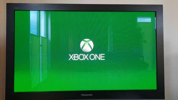 After seeing the Xbox one X logo a loud shout out "YESS!!" came up... That's cool I didn' even have to change a chip to get it working that was a cheap repair... The next questions is why I'm buying a Xbox one x? I'm a playstation guy. The reason for that is that I know there is a problem with repairs of the Xbox one x and also on Xbox series x. The problem is on the upper picture #4 the ESD Booster iC chip. You can't buy this ic. if this is broken the Xbox is a brick and can't be repaired (except of Microsoft of course). There is a possibility of bypassing this chip but then you do not have a ESD protection anymore also you aren't able to display 4k anymore. So the idea is to do a replacement PCB for this chip. After reading the ESD booster datasheet for the Xbox one I know what the iC is doing so creating a replacement PCB isn't that hard. So next step is to desolder this iC and creating a replacement PCB for it. |
| 12.04.2022 ultraDev |
Two days ago I had a talk on irc in #atariscne and ppl were asking when there will be a Linux x64 support for ultraDev. Well I do not have a Linux machine. First idea was to create a USB stick to boot from. After some browsing on the Ubuntu page I found a WSL Ubuntu. WSL is Windows-Subsystem f�r Linux means you can install the WSL version of Ubuntu and after it you can execute native Linux stuff on Windows. A bit like Wine on Linux but just the other way around. I liked the idea and installed it immediately. Unforunately I had real problem to get this to run or better to get internet access to run. in the end it was the windows file compression which is activated on my hd. The problem here was the %temp% folder which was compressed too and ended in a network is unreachable in the WSL environment... meh. Anyway... after this was working fine gcc install and download the USB driver libs for my USB ic pling compile and after about 10 minutes I had a Linux x64 version of ultraDev. AWESOME ;) tin and Troed tested it a little and it seems to work fine. Double awesome... ;) Pretty nice is that I can create the Linux x64 version in my automatic build script which creates all binaries and finally a release with one click. Means next release will support Linux x64. I know quite a few ppl are waiting for it. |
| 01.04.2022 ultraDev |
Some bad news (no 1. of april joke). I'll stop producting ultraDev for a while now. More infos you can find on the preorder page (Click for the bad news) |
| 29.03.2022 ultraDev |
Started to sell ultraDev on eBay. if you saw and wondered why it costs 65 Euro (incl. shipping) well I added the eBay commission to the price. I was hoping the buyer would buy it over my page but hm didn't work. There of course I still offer the cartridge for the old price. The ultraDev was sold after some hours I'm happy. Talking about the prices... Unforunately I have to rise the prices for ultraDev soon. Chip shortage finally reached me too. The prices for the iCs rised quite a bit. For example the FPGA is now 35% more expensice. That's very sad. But I have some iCs left in my desk to build up some ultraDevs... not many but anyway. So if are thinking about to buy one you should do soon... Otherwise u'll have to pay the new price. How much it will be I have to see. Talking about build up... in the last days I build up two new ultraDev which I'll sell on eBay after my traditional tests... Even some code on ultraDev ok already some time ago. I started a new feature tin wanted to have. As you maybe know you can upload a new 68k firmware to the cartridge. But it is lost after the Atari is switched off. if you did changes to the firmware and it should stay resistant even after a switch off this will be the solution. Means the custom firmware stays in the SPi flash until you erase it or if you reflash the FPGA firmware. Changing the 68k firmware is not possible for normal users. The 68k firmware is included in the FPGA firmware and can't be changed. What I'm doing (or better will do) I check a special position in the SPi flash and if it has something except of the init value I load the SPi flash data to the 68 firmware space. Ah damn I really have to release the 0.57 of ultraDev finally since it has quite some new features. The 0.56 version is from 10.01.2021 over a year uhh. But well the 0.56 version is pretty stable... Someone said "never touch a running system ;)" |
| 09.02.2022 ultraDev |
Today I sent the last ultraDev cartridge from the pre orders *fireworks* ;) A few thoughts and retrospective about the project... ultraDev has been a quite successful project. I sold more than I initially planned or expected. Of course the project is not over yet and you still can order one but it's a nice feel not to have something in your mind you need to finish because ppl are waiting for it. I know some ppl were waiting really long I mean I announced the project on the dhs board in november 2019. The first cartridge was send out on january 2021 to a normal buyer (beta testers got the cartrige earlier). Wow over a year after the announcement.;) And still it took almost a year to deliver the last cartridge. But I decided not to send cartridges all at once. I build up a few and then I contacted the buyer and when he is satisfied I contacted the next. This was to reduce support effort. Also testing the cartridges took quite a bit of time. I never sent a cartridge out to ppl which was not tested at least a few days during coding sessions. Later I used automated tests to ensure the quality. But it was worth no cartridge came back because it does not work yet. Well after the announcement alot happened. Of course getting the cartridge to run on all Ataris and Tos versions was a challenge esp. when you don't have the hardware ;) After building up the first cartridges for the beta testers I recognised very fast I need too long to build up the cartridges. Soldering all by hand forget it if you want to build up more than 2 ;) Esp. soldering the big amount of the capacitors are a pain in the ass. So I needed to get into reflow soldering. With reflow soldering you have a stencil which enables you to print the solder paste to the PCB. After printing you can place the components and finally you bake (reflow) it in a oven. First PCB with this technique looked like this: 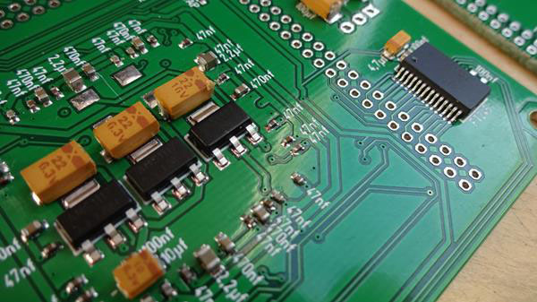 I was really impressed that looked absolutly like professional made PCB. Unforunately to get this to work in that perfection level it took quite some time. One problem was to create the stencil. The stencil is a foil which is cutted with a silhouette cameo (cutting printer). Unforunately printing out PCB is not supported. I had a tool which was able to print out PCB for a different cutting printer but that didn't work with my printer. So I had to get into the format for the cutting printer. Yeah that's fun. Also the cartridge change alot till it was final first one looked like this:  I planned to use the Waveshare FPGA board but it turned out that updating the FPGA firmware is alot of work. And I never got it to run in a acceptable speed. The update needed about 10 minutes. That sucked alot. So I've deviced to create an own FPGA board which uses a SPi flash to hold the FPGA firmware. The SPi is alot easier to programm. And besides the Waveshare FPGA board quite expensive. 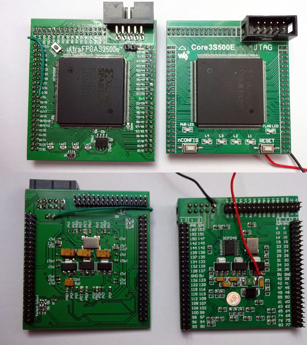 On the left the new on the right the Waveshare board. To optimise build up speed and costs I created a new revision of the cartridge (that black one) which combines the FPGA board and the cartridge to one PCB. The initial version of the cartridge only beta testers have. But it's fully compatible and still working and will work with future versions of the cartridge firmwares. During the delivery phase I changed the PCB design of the cartridge twice... I guess no one recognised ;) Basically no hardware changes more stuff which makes my life easier during build up. interesting is that about 43% of the ppl who ordered a cartridge ordered another or more cartridges after the first. And there are some mad ppl who have 4 cartridges ;) Really nice to see ppl are finding the project useful. in the last days I asked myself if I would do the project again? would I sell it again?... Hm ... I guess not. Creating ultraDev was unbelievable alot of work designing the hardware, coding the fpga/68k, coding the command line tool (for pc,mac and rpi), getting the cartridge production workflow reliable and finally build up all cartridges. Also alot of work for the beta testers who helped me alot with bugfixes (thanks ggn, tin and daniel). Of course I earned a bit with the project. if I count the hours I invest in the project well ;) I guess a worker in bangladesh earns alot more. To earn money it's better to do over hours at work but I do not complain I learned alot how to manage such a project also it was a good thing to get into FPGAs. And that was the reason of doing it besides of using it by myself. I'm using it since about november 2019 alot every day. Creating the cartridge for that price was a challenge. Well as a private person you do not get discounts on componets. Quite funny I received some Emails from ppl (2 or so) who said yeah cool project but too expensive. WTF. I'm not Apple which produces millions of devices... anyway. idiots... But I think it was worth without selling ultraDev never got the perfection level it has now. I mean in my initial annoucement in 2019 basically the cartridge filled my needs. And of course I need to thank all buyers... Thanks guys for supporting the project. |
| 01.02.2022 ultraDev |
Seems ultraDev is running on M1 Macs without any driver install. Ok not fully tested yet but uploading prg-files seems to work so far. Puh that are good news. Already expected I need to build a M1 version... Currently I'm working on the last pre-order. Nice. Last week I build some new ultraDevs which I'll offer on eBay. Let's see how this works out... interesting seems no one tried ultraDev to upload PRG-files on a mono chrome monitor. That didn't work at all... Luckily the fix wasn't very hard. Maybe a good idea to finally release the 0.57 version. Which I already use since a year now ;) There are quite a few new things included also CT60 support. |
| 24.01.2022 chip reball / new FPGA board / ultraDev |
I build up another PCB of my new Spartan 6 development board to see if I can reproduce BGA soldering. First try didn't work well it was more a problem of my dumpness. When soldering BGA you give the chip a small nudge to see if it snaps back. Ok the small nudge was more a big nudge because of too much coffee ;) And this displaced the BGA anyway forget it to solder the BGA now makes no sence. So I removed the chip and cleaned all up and resoldered another FPGA. This time all went fine and the board works fine. Means I can reproduce niceness... Due to the unsuccessful first soldering I have a BGA to reball ;) Tried this today again but I had some problem with it. The BGA I reballed on saturday had a pitch of 1.27mm and balls were 0,76mm hm that was somehow easier. The FPGA BGA has a pitch of 1mm and 0,55mm balls. Reballing this chip needed quite some tries somehow the balls were are always blown away and I was already using the lowest air flow for the hot air gun. I recognised I reduced the distance of the hot air gun too fast to the chip. if it is too fast the spreaded flux does not stick the balls enough. When you do slowly the flux gets really sticky and keeps the balls in place... Currently I'm preparing/testing the last two pre orders for ultraDev. Puh that have been quite a bit of work to work on the list. if these are done will start to sell on eBay. Not sure if someone will buy it. But let's see ;) |
| 22.01.2022 chip reball |
Today my new toy arrived: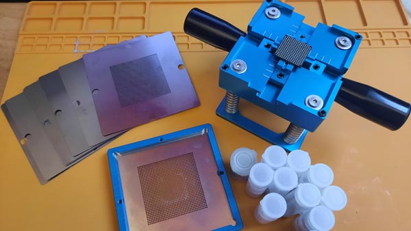 This is a reball station. Means when you desolder a BGA chip and you want to reuse it you need to add the small soldering balls under the chip back before you can use it. Or if you have cracked solderings under the chip because of too much heat you need this to readd and resolder the chip. For example a blue light of death (blod) on ps4 is often a problem that the APU does not have 100% contacts to the PCB anymore. With this tool you can repair. Or better it's one of the tools you need to repair. The reball station comes with standard stencils, solder balls and the station itself. Costs about 60? on brother ali. Normally 2 flux are included but unforunately they did send... Suckers! anyway... So it's reball time ;) I selected a 56301 DSP as a BGA package. Which I never used and I think I'll not... 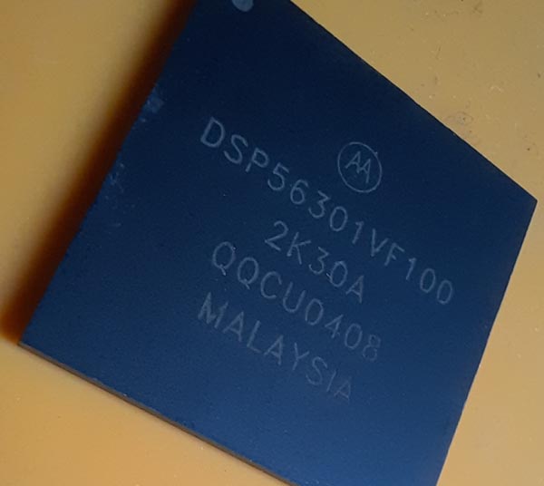
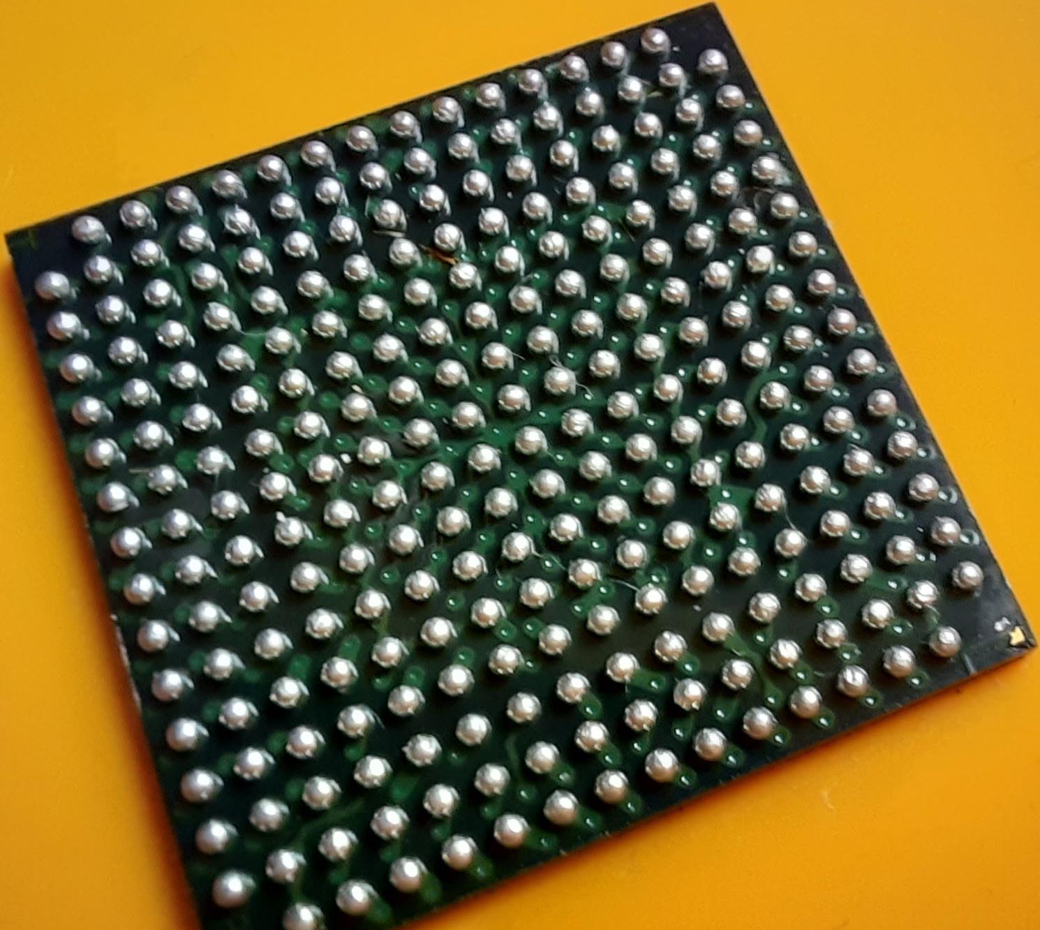 Before I can reball of course I need to remove the old balls. Flux and solder wick is your friend. On the right the already removed balls. But that's not good enough I did a second pass to remove all soldering. That's important solder must be fully gone. The chip is already in the holder of the reball station. The frame with the stencil is now added. 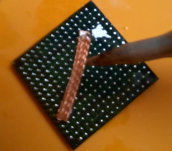
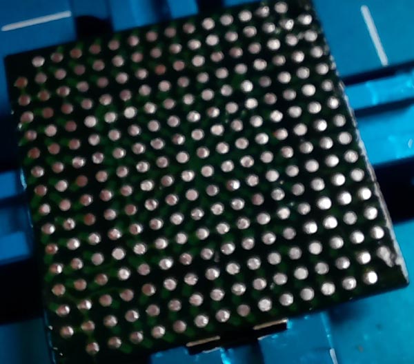 Next is to align the stencil to the BGA pads. When alignmented is fine you can add balls to the frame. On the left you can see the balls fall into the holes. As you can see the stencil is alot bigger than the BGA chip. I used some tape to avoid balls are falling into areas where no chip is. important is that add really a bit of flux to the chip. This will keep the balls on the pad. if all is fine press down the entire thing from the upper. This moves the chip down and you can remove the upper frame. On the right you can see the balls after removing the upper frame. Nothing is soldered yet!. 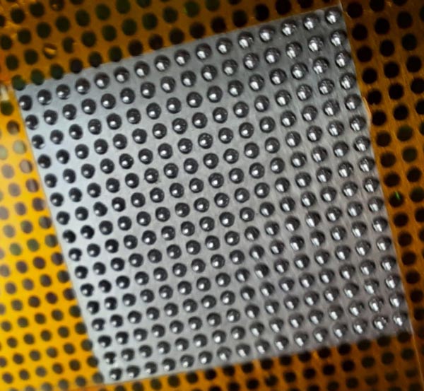
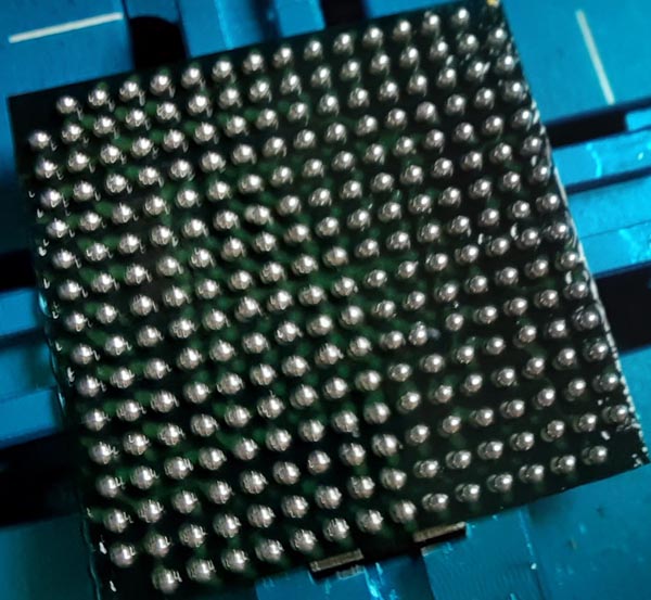 Now you need to use your hot air gun and heat up the chip slowly from the upper starting at 15cm and slowly go down. if the balls are melted add some flux and resolder again. End result looks like this: 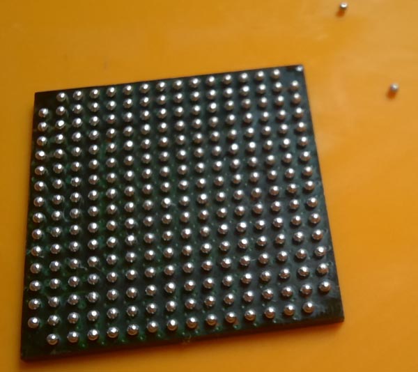 I'm satisfied with the result. Not too bad for a first reball. These fucking solder balls are now everywhere on the desk ;) Round up of reballing. it's no big deal to reball a BGA chip at home. But it really needs some exercise. The end result is the 4th or 5th try. in the first trys I always had the problem that the solder balls are connected to each other during soldering. The reason for this is too much flux. in the end I only added a little and spread that over the iC with my finger. Less is more ! The reball station works pretty good. The feature that you can move down the BGA away from the stencil is really cool. This helps alot to remove the upper stencil frame without moving the balls on the BGA. Next challenge would be to buy a PS4 with blue light of death and resolder the APU ;) that would be fun... But you need to know which kind of blue light of death the PS4 has. You can recognise how long the PS4 stays on. But forgot which was a possible APU resolder problem. Anyway I have a PS5 no need to buy a PS4 ;) |
| 19.01.2022 new FPGA board |
Today I recognised I'm still bound to the old software from Xilink. I though a Spartan 6 which is still in production is supported by Vivado. But it isn't. Anyway. I didn't do this to use Vivado more to get additional place in the FPGA. Ported today my bigger project to Spartan 6. And it works without problems. That is now finally the proof the new dev. board works as it planned... The port wasn't a big deal tbh and it was done in an hour. Unforunately it didn't work and rest of the time I was searching why. But in the end I just mixed up 2 lines... meh Really nice with the new Spartan 6 the project needs about 56% logic before with the old FPGA I was at 97%... Also it uses only 38kb of 64kb ram means 26kb is free...With the old FPGA I only had 2kb left... niceness. That all went to good to change to a BGA chip and in the end to Spartan 6 I'm really happy. I expected some deeper problems... yes ! |
| 18.01.2022 new FPGA board / ultraDev |
Today 2 more FPGA arrived. I ordered from two sellers just to be sure I get some. Well ordering from china you always risc to get fakes. Tbh I really ordered alot now and never got fakes or better I did not recongised them because they worked fine. Today I continued a bit with my BGA Spartan 6 board. Unforunately I recongised a bug in the layout. The on board HDMi will not work :/ Yeah I connected the HDMi to the wrong side of the FPGA. My FPGA only can provide TMDS (Phy Layer for HDMi) on the upper and lower side. I connected it to the left. Great Job!. Damn what a pity... The shit is I read about the upper and lower side one hour ago I layouted the stuff. And forgot it. I'm old ! But no big problem some time ago I created an extension board for my FPGA experiments which is able to output HDMi with a sil9022 chip. Of course the new dev board fits to old extension board. After some smaller changes of the FPGA code my TV displayed this: 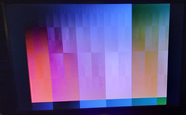 Nothing brainblasting but showed again the FPGA board seems to work. Booting the FPGA from a SPi flash seems to work too... Cool ;) I'm really happy I can continue now with my other FPGA project. That it works that good I did not expect. Stepping into a new generation can often produce some problems. Esp. when using BGA chip for the first time. Ok maybe the problems will appear in my other project. But I'm optimistic So I really can start to port the Spartan 3 code to Spartan 6 now. During xmas and new year I soldered some ultraDevs. First I'll deliver this week. I'll contact some of you soon to ask if you still want it. |
| 17.01.2022 new FPGA board |
11AM the door rings... Postman is here... and delivered this: 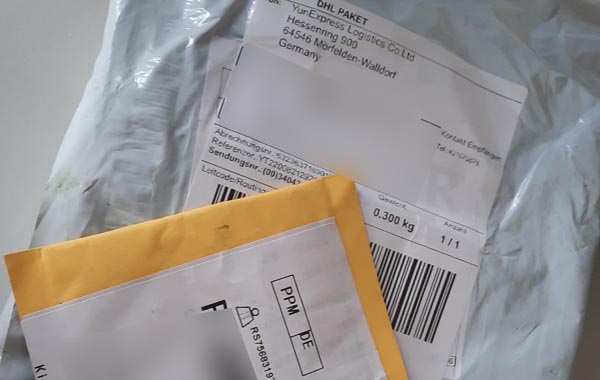 What could that be? Nah just kidding... Of course I know what it is ;) 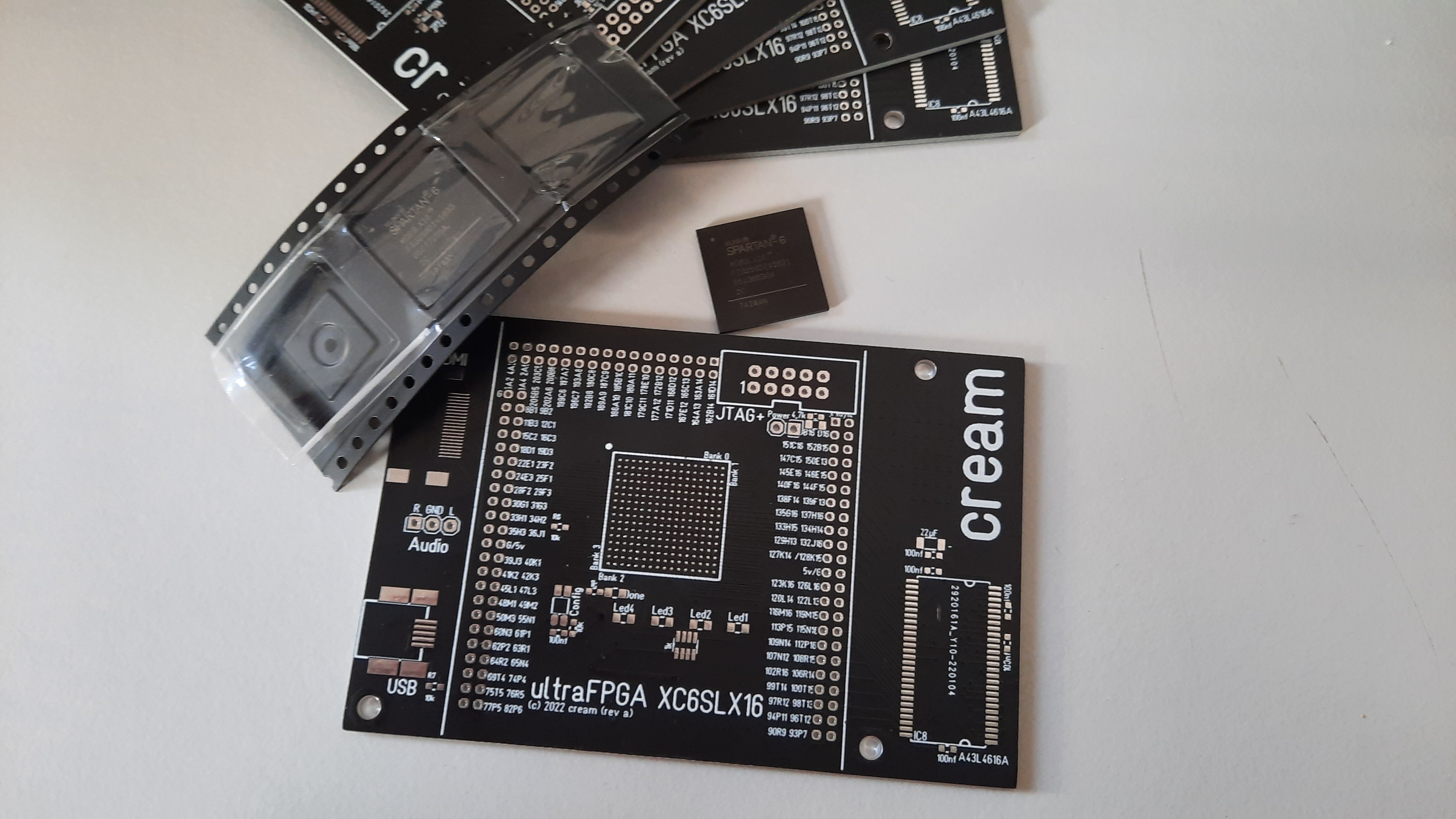 it's my new PCB for my Spartan 6 development board I created and luckily the FPGA chips at the same time... That's great... I did a small special blog of how the build and how the first soldering of the a BGA chip worked out. (Build up blog click here) |
| 07.01.2022 new FPGA board |
Today my new toy arrived: it's the PCB heater I talked about earlier... That thing comes from China means I'll not use it before I opened it ;) And as expected the ground is not let's say optimal: 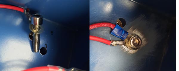 On the left the original on the right the better one. I also added a direct ground to the top of the devices by a cable for savetyness. That's a typical problem with china products... anyway. Beside this I did some more mods. The thermocouple did not have a good contact to the upper plate and I added a switch to switch on/off the heating. Now it's useable ;) Nice is now I finally can change the battery pack in my phone by myself. Newer phones are only possible to open with a heating plate. And my new hot air soldering station arrived too. Nothing special I guess the cheapest you can get. Of course opened it and smaller fixes... 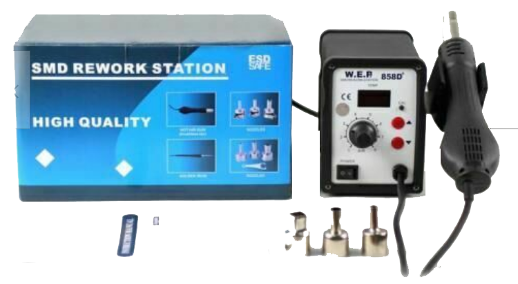 So now the PCB and the FPGA is missing before I can build up my new board... |
| 06.01.2022 new FPGA board |
A step into the next generation...;) And it looks like this: 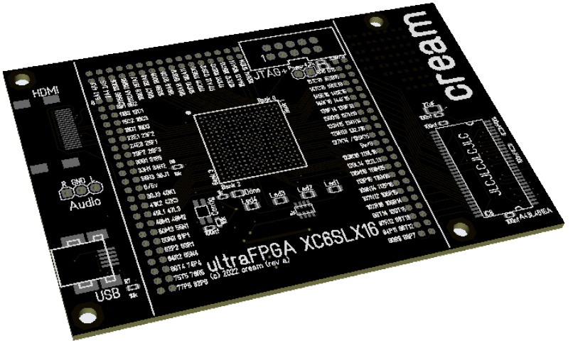 in an another FPGA project I unforunately reached the borders of my Spartan 3 (500e) FPGA I currently use. I spent quite some time to reduce the size of the code but for that what I want to do it's too small. Damn! Well then you normally use the next higher one. Yeah that's the way to go but unforunately there is no bigger FPGA with pins. All bigger Spartan 3 are only available in BGA packages. Which means all pins are under the ic:  Shortly before xmas it started to read some stuff how to to solder these chips and how to create these kind of PCB esp. how to fan out the needed pins in so they are availble. Hm creating a new dev board for Spartan 3 did not make sense. it's outdated not in production anymore and well it's not supported by newer tools from Xilinx. So the goal was clear I need to create a Spartan 6 board. The package I selected has a pitch of 1mm 16x16 pins -> 256. One problem was of course to use these kind of packages you need a package for your layout program. I'm using a quite old one and of course the package was not available for it. Of course creating a new package is possible in the layout programm but this is a pain in the ass. With 256 pins it's really alot of work and error-prone. So I coded a small tool which is able to create BGA packages out of the datasheets from Xilinx for the layout programm. Great that saved alot of work. As a start I used my old Spartan 3 board and changed it to Spartan 6 with a BGA package. And surprised how easy it is to fan out the needed pins. 4 Layers makes it possible... So one problem is solved layouting the next is how to solder these chips. I use this reflow oven but I don't think I can solder BGA with that it only provides heat from the top but the pins to solder are under the chip: 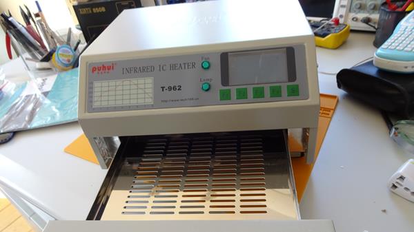 it's a cheap china thing a bit modded to work better (see below). Works pretty good for my normal soldering. All my ultraDevs are soldered with it. But for BGA I need different equipment. I need something to heat up the PCB from the lower side and finally solder the chip with hot air. That one I ordered. Means the PCB with the already placed BGA is heated up with the heater to dunno about 180-200�c the final soldering is then done with the hot air gun. Besides I also ordered a new hot air gun. Well normally I use a hot air thing from the hardware store. Worked so far but well for a BGA I need some more control of the temprature. Of course I expect the first soldering will not work fine I think. Unforunately resoldering a BGA chip is not possible like chips with normal pins. if you have a look to the upper picture for a BGA there are some small balls under the chip. These are gone if you desolder the chip. So the last tool I ordered: 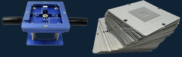 This one is to add the small balls back to the chip. it's called reballing. Really alot of new stuff new techniques to get into but really exciting stuff I really hope I can handle all here at home. if that all work how I planned tbh I don't know... There is no other way to find out than just to try it. 10 Years ago I wasn't sure if I can handle 0,4mm pitch iCs that is nowadays default so time for the next step... Unforunately something popped up as a real problem which I absolutly did not expect. The PCB is already in production... All tools are ordered. But getting the FPGA was getting a real nightmare. Spartan 6 is a device which is still in production and well we have a global lack of chips. And that got a real problem in the last days. Unbelievable. Alot of sellers on Aliexpress still offering them for a good price but each time I ordered they told me after some time sorry we are out of stock. I surely ordered from >15 sellers each time the same. Fuck. in the end I ordered a Spartan 6 for a price which is 6 times higher than the normal price. Holy fuck. I really hope they send me the right and working chips ... Still with me? ;) I guess not anyway no problem. I'll keep you up to date how the BGA stuff works... Even if you aren't interested in ;) |
| 03.01.2022 STE repair |
Long time no update...sorry (again) Some weeks before xmas my Atari STE got broken :/ it did showed a picture anymore on my TV set. After some measurements it was clear there is no horizontal sync anymore. The hsync comes directly out of the gstmcu means most prolly it is broken :/ So I fired up ebay and checked if the gstmcu (C300589-001) is available. Uh 33? + shipping that's heavy... But there was a second gstmcu C302183-002 mh which costs only 7,33?? it seems the old C300589-001 needs an external blitter the new one has a blitter included. After that I tried to find out of the new gstmcu works fine in a STE? I only found one guy who changed from the old to the new gstmcu but it was for a Mega STE. But should work too..(I hoped). So I ordered 3 of the C302183-002. Shortly after xmas they arrived. So this blog entry is about to change to the new gstmcu. There is a forum which explains it for the Mega STE there they say the gstmcu must be soldered in rotated by 180�. DO NOT do this for STE. it seems the silkscreen on Mega STE is wrong but in STE it isn't. Just solder in that orientation like the old one was ! This one needs to replaced. I removed the upper capacitor just because of the hot air. 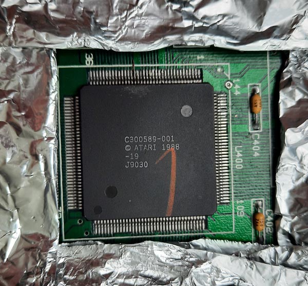 You really have to be careful with the PCB you can easily kill some traces... after cleaning it looked like this: 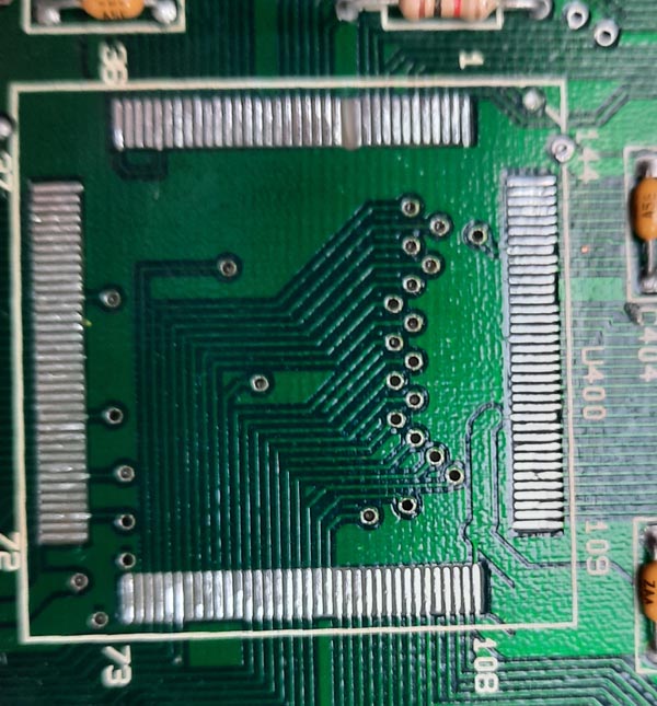 The new chip... I ordered it from atarifreakz. 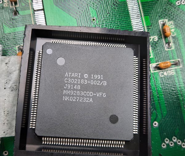 Soldering went fine. 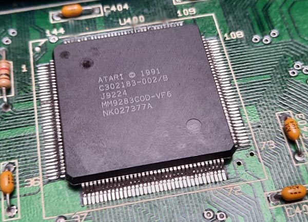 Very important part is to remove the blitter since the blitter is included in the new gstmcu. And you need solder in two solder bridges (on the left). 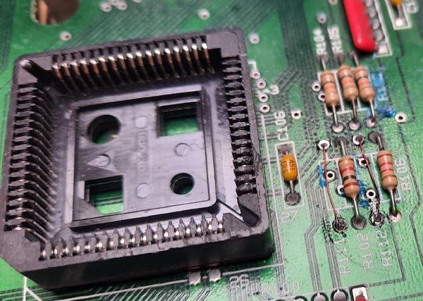 After some cleaning and switch on it looked like this:  Great... That's alot better than a black screen ;) |
| 18.10.2021 ultraTos / ulraDev |
Long time no update...sorry @ultraTOS Unfortunately my final test with the beta tester didn't work very well and took quite a bit of time. Results are we could not get ultraTos to run on the beta testers STE machine... He sent it back to me I just plugged it in and it worked fine... That's bad and a bit frustrating... Unforunately this leeched all my motivation currently... Well currently I have no real idea what's the problem. The beta tester is too far away to visit and I can't do a release with this result... @ultraDev I was working a bit on CT60 compatibilty... works a bit better but Bugaboo seems not to work very well anyway... dunno if I can fix that... |
| 03.08.2021 ultraTos / ultraDev |
The all 4 build ups from ultraDev are working now. This is nice. Currently I'm doing the long time tests. I Tested yesterday all already build up ultraTos PCBs except of two they work fine (one flash memory is not available it's surely a bad solder). But testing is not fully done yet. I just did the flash and long time test. That automated test are a real help good that I did this. So basically only the jumper test is missing means if the pre configed boot up and if the setup for the Eprom config is working fine... One ultraTos is out to the new beta tester let's see how the result it ;) |
| 29.07.2021 ultraDev |
I started 4 new ultraDev build ups today. 2 are fully done and working so far. Of course needs a long time test but anyway... The new revision of the PCB is alot easier to build up. I always had problems to do the soldering for the FPGA correctly. The pads have been too short. With to short pads it's harder to remove short cuts with soldering flux... Sure I use reflow to solder all stuff... A PCB never comes out of the oven without having some final soldering removing some short cuts or bad soldering. But still even if I have to do a final touch it's alot faster than soldering all by hand. Well I only have a semi professional reflow oven and my soldering paste I use is a bit cheap... Maybe the the stencil I use for printing is not optimal maybe too much soldering paste on the pads but this only happens to the FPGA. That's ok for me... With some good soldering flux it's no big deal... I think I'll do a small video if I build up an ultraTos PCB again soldering the CPLD with 0,5 pitch in just a few minutes... The price for the farest away delivered ultraDev goes to.. ... Los Angeles funny in 2017 I've been there and my flat was just a few km away from his place... Ok not delivered yet tbh but I'll in the next days... Puh sending stuff to US is not that cheap if you do not want to wait up to 60 days (sea shipping)... Currently listing to the music disk signals from dhs. That's the first part of the long time test for one cartridge. I really love the music disk just great. Hm have to download no signals have to note that... |
| 27.07.2021 ultraTos |
I build up another 4 ultraTos today. 3 were working after the first switch on unbelievable I never had that. Seems the new soldering iron is alot better... Unforunately it seems one Ram chip is again broken. Slowly I thinking the Ram chips are broken sometimes. But hard to proof that... anyway... Today I included to the flash tool a verify that wasn't included yet. I also started to code some automated test tools like flashing all Tos slots and at the end a verify. And a stresstest which reads out the entire time the Rom and compares it with an image in the prg file. That I plan as a long time test to see if all is working at least for a few hours or so. I selected a fresh and new beta tester for a final test esp. to test the manual and stuff. Hope I can send ultraTos over next week... Alot of the ultraTos preorders are already build up but untested yet. Or better the PCB basically works means it boots from the first eeprom and that's it. Of course a bit more testing is needed. I hope the automated tests help a bit to speed that up a bit... |
| 26.07.2021 ultraTos / ultraDev |
Not many updates... Well it's summertime enjoying the sun and the beach ;) And besides I was working a bit more on my new Atari hardware project... But I did a new revision of the ultraDev PCB so it's available again. The new revision only have smaller changes which make it easier for me to build up. Today I investigated why some build ups of ultraTos do not work. I connected a logic analyzer and recognised the ram chip is broken. Sometimes some data lines of the memory just do not work. I checked again with the logic analyzer if the access is inside the specs and it is. That sux really about 30% of the chips aren't working until now. That's really odd no clue how this happens. is it a problem of the reflow does the iC gets too hot? Or maybe a electro static problem during build up? I'll try to solder the chips now by hand and touch a grounded devices before maybe that helps. Anyway... Never had these problems... I mean the same ram chip I'm using since almost 15 years now and I never had not working chip... The only difference is I didn't do reflow in the past that's new mh. But by changing the ram chip I could get all already built up ultraTos PCBs to run. That's nice... I'll do an extra round with an additional beta tester I think to just to be sure it is really working fine and installation is as easy as possible... |
| 29.06.2021 ultraDev |
I was working a bit to improve the soldering results of my reflow oven means calibrating the oven again and adjusting the reflow curve. Yesterday I build up two ultraDevs and the first is already working the second is not fully build up. Maybe the changes helped a bit... Unforunately the weather and EURO 2020 slows down the entire process alot ;) |
| 22.06.2021 ultraTos |
Some good news. The ultraTos build up problem haven't been a project killer ... yet. I Could get except of one all build up ultraTos PCBs to fly. Puh ... Yesterday I was in really bad mood and I already had thoughts about to skip the project. But luckily I could motivate again today to trace down because I know the stuff is working fine. I'm using it since monthes now... The problems have been quite a few. I recognised I set the speedgrade for the CPLD in the ultraTos project wrongly. I used -5 my CPLD is -10. The speedgrade is the pin to pin delay -5 means 5ns -10 10ns means the CPLD design expected an alot faster CPLD. Bahh what a beginner mistake... Unforunately that wasn't the only problem. There have been still some bad soldering joints at the CPLD and ram. Luckily I have a soldering station now ;) So I increased the temprature by 15�C and it worked alot better... Damn I never had such problems soldering iCs unbelievable. I guess surface finish (tinning of the solder pads) of the PCB is lead free I ordered leaded. Lead free needs alot more temperature to solder. Hm dunno I'm to very into lead free soldering... I luckily I soldered some time ago a small PCB which makes it possible to connect the ultraTos PCB to the cartridge port of the Atari. 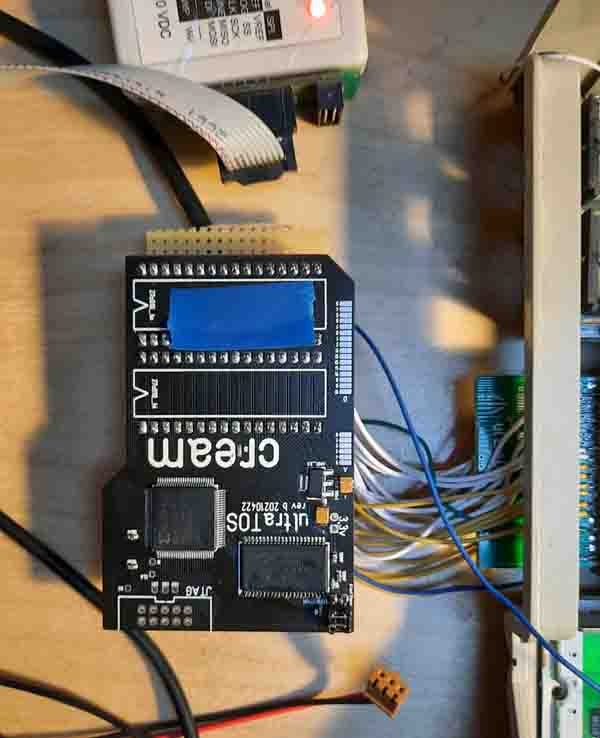 Unforunately the cartridge port can only address 128kb the only half of what is needed but anyway still a great help. I really the builds are working a bit better in future. Currently getting a ultraTos PCB to run is a nightmare I mean I already solder ram and CPLD by hand because the reflow soldering does not work very well. Maybe I have to calibrate the reflow oven again also maybe I need to adjust the the temperature curve again... Anyway Btw. my logic analyzer did not arrive yet... Great DHL it's in my home town since 5 days and they aren't managed it to deliver it... Thumps up! |
| 21.06.2021 ultraTos |
On Friday I've got my new toy:
 Hm... unforunately the last 4 ultraTos PCBs I build up do not work. I was hoping it was the problem of the not good soldered joints. But seems to be a different problem. Today I'll get my logic analyzer (hopefully) and then I'll investigate that problem. I guess it's something wrong with the ram chips maybe faulty or maybe there is something wrong with the access to the ram chips. Dunno yet both would be really bad. I did some test designs for the CPLD first one just outputs patterns throu the rom port like $5555 $aaaa $0000 $ffff and this works fine. Second one outs the adress lines to the data lines. Both looks ok. Third test design for the CPLD writes the patterns to ram and normal read out. And this seems not to work correctly some bits of the test patterns aren't outputted to rom port correctly. Let's see if the logic analyzer helps here. I'll try to slow down the ram accesses. Tbh I can't imagine this is the problem because the ram chips are 100mhz and I'm using them at 50mhz. Anyway. I really hope I do not have to change something to the CPLD design. The CPLD chip is absolutly filled I even can't add one new state to it. I really hope this is not project killer... |
| 17.06.2021 ultraTos |
My soldering output of the last days:
 The ones with the blue sticker are already working the other PCBs aren't fully done yet. The already working ones aren't fully tested yet. I always do a long term test. Usually I test each device about a day. Let's see if I can wake up to life a few more today. Depends a bit on the hotness in my rooms. Weather is really great currently in germany maybe better go to the beach ;) By the way I'll sponsor one ultraDev and one ultraTos device as compo prices for the Sommarhack 2021. So get active and write a demo ;) |
| 14.06.2021 ultraTos |
Started to build up 5 ultraTos PCB in the last days. The first I could finish today... And well it did not work :/
The Atari booted but showed this screen: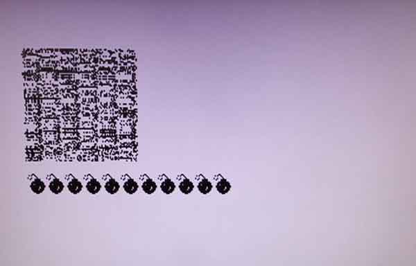 No this is no QR-code you can scan ;) Oh noes... I already thought damn I'm too stupid to build up an ultraTos PCB. I know the Atari logo is somewhere in the end of the rom. So I started to check all higher address lines. No success Resoldered the CPLD again ... mh No success... After some time I tried to plug in a already finished and working ultraTos. Same behavoir... Putting back the EProms. Same behavior... WTF? is my Atari broken? Ah well after some hours I found or better remembered I changed the EProm config last week to test the original Roms and the jumper of on the ultraTos PCB was not set correctly. Meh Maybe a good idea to read the ultraTos manual again ;) After setting the jumper it worked fine. Double Meh I didn't thought of that the jumper just changes the from where the A16 signal is selected... But this is quite normal when you build up a PCB more than once you get to know which bugs during soldering or misconfigs can happen. For ultraDev I already build up some and I know what behavoirs result into which problems... But not ultraTos currently but just a question of time... But that is good to know if the EProm config is wrong the Atari shows this effect. Good to add this to the manual... Unforunately for later batches of ultraDev or ultraTos I have to lift the prices. Most of the parts for ultraDev and ultraTos are comming from China. Currently I only have to pay taxes when the price + shipping is >25 Euro in Germany. On first of july this will change and I have to pay taxes on everything + additional costs from DHL. Means all getting more expensice > mh I guess about 22-25%... Sorry but I can't change this... Of course the already pre ordered ppl will pay the price of the pre order day... |
| 11.06.2021 ultraTos |
A rather disapointing week more or less... Build up two ultraTos and both did not work meh... At least I have some test designs for the CPLD if there is a problem in build up to trace down the problem that's good. The first I could get to run and ended in the result that the ram chip was faulty that's not good. I really hope this does not happen more often... Maybe it's a problem in the CPLD code? To investigate I ordered a logic analyzer finally. But I really can't imagine I'm out of specs during using the ram chip... I mean the ram chip is able to handle 100Mhz and I'm using it with 50Mhz... Maybe the logic analyzer can fully proof the ram chip is broken... The second ultraTos PCB I did not investigate yet why it does not work. But somehow soldering is extremly hard to do with theses PCBs maybe my soldering iron is not warm enough anymore...hm anyway During testing ultraTos I recognised it's not possible to boot up into Tos 1.62 with the boot tool during runtime. When I directly booted into 1.62 it worked fine. Also a reset after the boot try worked fine. Luckily it was a problem in the 68k booter. Any heavier bug in the CPLD could mean a real problem. Currently it's absolutly filled and I can't add any new stuff to it. |
| 06.06.2021 ultraTos / ultraDev |
Back from vacation. These two weeks have been really relaxing and filled up the battery. Best is to use this energy to do something you aren't not very motivated to ;) I could finish the manual for ultraTos today. I already started some time ago but I was not satisfied with the installation part. So I skipped that fully and reworte it with alot of pictures. Some days ago I've got the last order now for ultraDev means it's sold out now... Currently I'm not planning to do a second batch. Well I never did the project to earn money. TBH I'm earning not much there considering the work I put into to build up and test the cartridge. To earn money I better do some overhours at work ;) I'm testing really much before I deliver and luckily no cartridge came back until now that's nice. Not all cartridges are delivered yet but anyway have been a nice project and I learned alot about doing such a project. Of course there will be updates for the ultraDev software. |
| 17.05.2021 ultraDev / ultraTos |
All ultraDevs so far have been deliverered (except of two). I'll do a break now last weeks have been exhausting (work and ultraDev wise).
My vacation starts next weekend (2 weeks) after that I'll start to build up the ultraTos PCB.
|
| 05.05.2021 ultraTos |
Today the new PCBs for ultraTos arrived... Looks like this: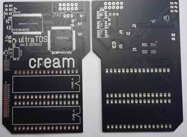 Ok not very sharp hm anyway ;) Of course I could not resist and had to build up a PCB to see if the new revision works fine. And the Atari boots that's nice more I didn't test yet but I'm pretty sure the rest will work too... Most interesting for build up is I do not need to cut traces (this was needed for some later features I added after I ordered the first revision) also I had some bugs in the layout so I needed to solder traces that was stressy... The outline of the PCB is now more perfect means it fits alot better: 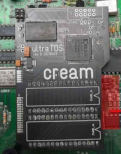
Ok the PCB needs some more cleaning just seening ... hm anyway... As you can see (red area on the picture) you can now access the resistors/jumpers for the rom select esp. resistors made problems because of the distance to the PCB... So let's see I need to deliver some ultraDevs next and then I can start to build up some ultraTos PCBs. |
| 21.04.2021 ultraTos |
I ordered new PCBs for ultraTos today. Well the new revision has some advantages: a) it offers real solderless plug and play (so far you were using original Atari roms or 27010/271001 Eproms) b) there was a small space problem with the old PCB and the w102 and w104 resistors/jumpers. Since the old PCB was directly over the them it was a problem of space. So the new revision is milled there (you can see on the lower picture on the right side). 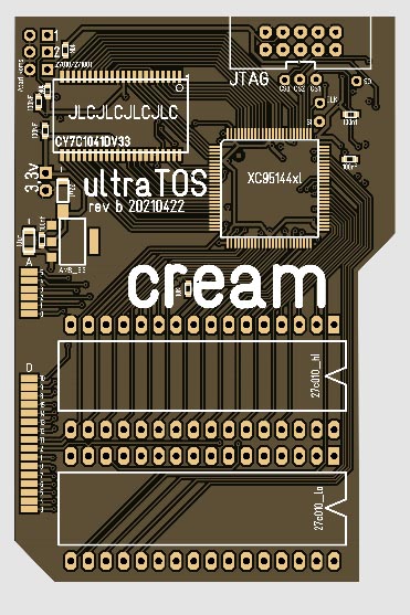
I think I'll only deliver the new PCBs since it produces less problems during installation... |
| 16.04.2021 ultraDev |
Currently I'm building up the last ultraDevs for devlivery... OK can't finish all because I need to wait for some FPGAs but anyway... Puh that was quite a bit of work. So I'll have some time to build up some ultraTos next... if I remember me right there are 2 ultraDev cartridges left which haven't been sold yet I think I'll not do a second batch currently that just takes too much time... Besides a new release for ultraDev is comming up soon... |
| 14.04.2021 ultraDev / ultraTos |
it have been a bit quite in the last time... Well had had some vacation and I'm building some ultraDevs to deliver... Unforunately 4 FPGA I ordered had extremly bended pins I guess I can't solder them. Fuck did see that on delivery... So I have to order new... The new connectors for ultraTos arrived now... Seems to fit very well. The problem is there is not much space under the floppy but seems to fit with the new connectors. That's nice... |
| 29.03.2021 HDMi Board / ultraDev / ultraTos |
Oh man last week was really frustrating... After I've got the HDMi board to run it didn't work on the next day. I desoldered and soldered the HDMi chip 3 times and in the end it didn't work... On thuesday I gave up and said to me fuck you... At weekend I had the idea mh maybe the soldering is not 100%. Of course I soldered the pins around the chip 10 times but the HDMi chip has a big ground plate which I need to solder in my reflow oven. You can see here: 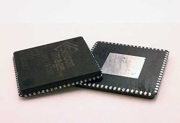 And yep and that was the problem or better it looks like this. Seems the oven does not get hot enough to solder the plate... My solution was a bit prehistoric tbh I just drilled a hole through the PCB and soldered it with a small cable...;) Anyway that worked... I really hope it stays working... Besides that frustrating stuff I started to deliver the first ultraDevs... Really hope they are working fine... Good news for ultraTos the new connectors are already in germany hope to receive them next week maybe even this week but stuff receiving from China always needs some time even it is already in germany. Seems they haven't been on the ship in the Suez canal... That's good... |
| 18.03.2021 ultraTos |
I included today the idea I had yesterday. Now it's possible to install ultraTos without soldering means you can select the Eprom setting (27010/27c1001/571000 or original roms/531000) by a jumper on the ultraTos PCB. if you have another Eprom setting you need to solder but these should be the most common setups. Getting this to run was quite tricky. After I did the changes for the CPLD the fitter told me my CPLD is full. Hm that's bad but I could find a workaround includes cutting some traces on the PCB anyway works that counts. Good that I did not order the new PCBs for the second batch so I can include the changes to the new batch. One ultraTos is out to ggn I hope all is working fine... Besides I'm starting to deliver ultraDev next week... |
| 18.03.2021 ultraTos |
You can call me a soldering king. Well I changed to the Eprom config in my STE to jumpers unfortunately I cut a trace on the mainboard during desoldering. Great!... it took a while to trace that down anyway... So I recommand not to change to jumpers if you do not have good desoldering tools... But ultraTos fits fine with jumps if you cut the jumpers to 4,5 mm and using short jumpers. I'll add short jumpers to the delivery. Yesterday I had an idea how to make the installation of ultraTos a little easier. Currently you need to set your Eprom setting to 27010 eproms. if your Atari do not have this Eprom config you need to change the EProm config. Means soldering. That's stupid. ultraTos has 3 jumpers to set the Tos version to boot from. So it's possible to boot from all 6 Tos slots. I think I'll limit it to the first 3 Tos slots. So I have one jumper left. That jumper I could use to select which Eprom config to use. Means original Atari Tos roms or 27010 roms. That's maybe better esp. for ppl who aren't able to solder or do not have the equipment for this. I'll try later... Unforunately the new connectors are quite expensive in germany I'll order them in China which will take some time to arrive. ultraTos seems to work fine at tin's place these are good news ;) |
| 16.03.2021 ultraTos / HDMi board |
Good news @ultraTos. The ram chips finally arrived. Last week I sent ultraTos to tin. And it seems to work on his computers but two smaller problems appeared. if the STE has jumpers for the rom select the space is a bit limited. Have to check that later. Second problem are the connectors which do not fit in every ic socket. Ok that's no big deal I'll order some new. I'll send ggn a ultraTos too later this week ... so let's see how this works out. Unforunately time is a bit limited due to stress at work I guess this will not change this week. But I continued a bit with my HDMi board for my FPGA. Getting this to work was quite a bit of hm let's say pain in the ass ;) it's always a problem to get something new to run. There are alot of possible problems esp. with the HDMi it was problematic. in worst case you just get a black screen. Possible reasons could be wrong PCB layout , wrong setup code, problem in the i2c protocol and finally a problem in the display code meh. But I could get it to run. That's nice... 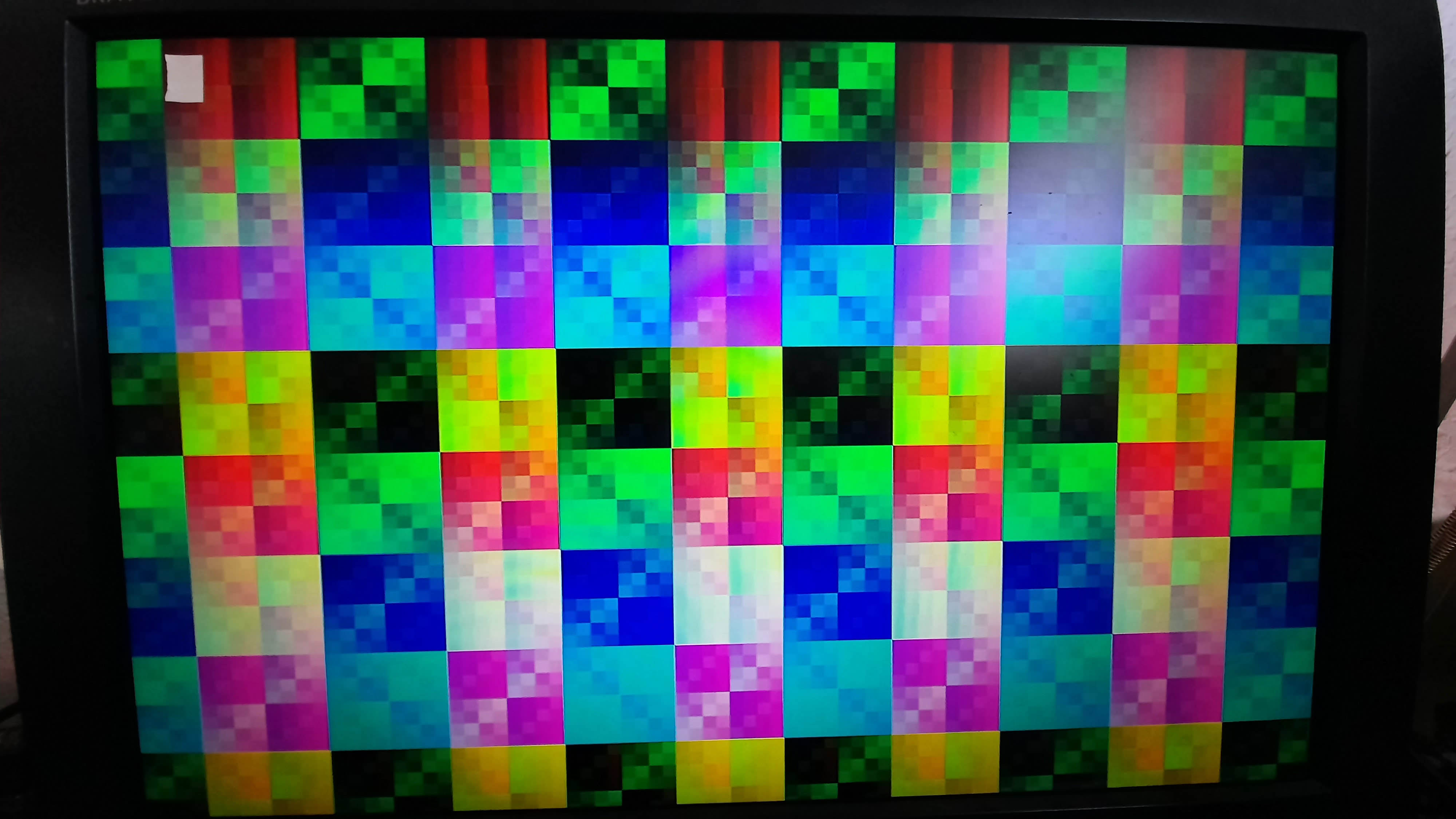 The setup of the HDMi chip via i2c protocol was quite a bit of work. Somehow I never liked i2c I always had problems with it seems I did not understand it fully. Esp. reading worked different I expected. And again a logic analyzer would have been really useful to debug. Maybe I have to build one for my own some day. |
| 08.03.2021 ultraDev / ultraTos |
I still did not get the ultraTos I build up to run anyway I'll skip this now maybe a faulty ic dunno. I'll work again on it if the ram chips arrived. But the second ultraTos PCB I build up works fine. That's good. Last week ended in a total not working state. That first ultraTos PCB did not work and during the week I build up 3 other ultraDevs. All not working. That was quite frustrating. All showed the same behaviour. The Xilinx programmer just do not recognise the FPGA. Hmm very odd. That could mean all FPGAs are fauly? This morning I recognised I forgot something ;) Before placing the FPGA I remove a little soldering paste of the first pins at each edge of FPGA pads. This makes placing the FPGA alot easier because you can see the pads and to adjust the FPGA alot easier to match the pads correctly. Unforunately I forgot to solder these pins. WTF I'm getting old. I soldered the pins now this moring again on one board and tataaa it's recognised. My FPGA has its JTAG pins are at the edges so it was clear it's not recognised without soldering. Puh I already thought the last FPGA order was faulty but at weekend I remember I already build up a ultraDev with one of the FPGAs. Anyway that's good ;) |
| 03.03.2021 ultraTos |
Unforunately I'm still having problems to get the new soldered ultraTos PCB to run. Debugging is extremly hard somehow a) because I do not have a logic analyzer b) you plug in the PCB to the STE and you just get a white screen. That sucks big time. So I tried find a better way to debug. My soldering job yesterday: 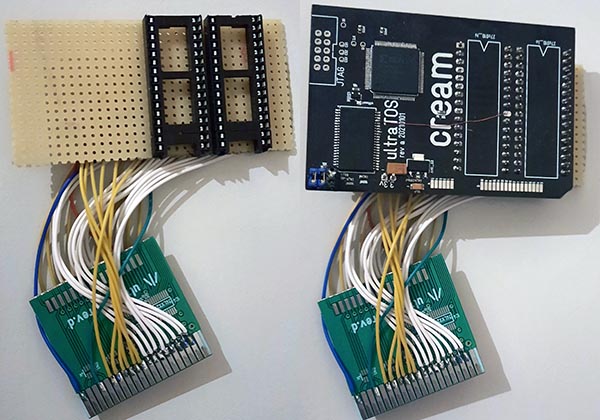 Looks a bit chaotic anyway ;)
 During a bath I had the idea why not connect the ultraTos PCB to the cartridge port? On the lower you can see an old ultraDev where I cut anyway the unneeded parts the cables connect the cartridge connector to the ultraTos. Ok sure the cartridge port can only address 128kb but at least you can see a bit better what is wrong even an automated test would be possible which checks a) all data lines and b) all address lines. Currently I only can address 64kb need to add some logic today to decode the rom3 and rom4 to a ce signal. Ok still 128kb are missing because the address space of the cartridge can only address 128kb. I think I'll do the last address line with a small switch. So the small test PCB already helped a bit whats wrong with the PCB. it seems booting up the Tos into ram works fine. Also ram and and accessing through the rom port too. it seems the 12bit of the dataline do not connect correctly... That was good step I'll trace down later... |
| 01.03.2021 ultraDev |
I did a small video today during build up of the ultraDev FPGA side:
At the end the entire PCB goes into the reflow oven and all is soldered on one step. it's replayed with 8x speed means the normal video is about 20 minutes. Very good is that the 8x speed hides a bit the shaky hands ;) Had a pot of coffee before I soldered that made the component placement extremly hard ;) That will be my new development PCB the other two I build up I'll send to tin as soon as I finished the ultraTos PCB for him. Currently not working. Ah almost forgot;) 
|
| 25.02.2021 ultraTos |
Unforunately less time currently. I tried to finish the 2 ultraTOS PCB I did last week. Hm unforunately I soldered in the EEproms wrongly so they committed suicide shortly after :/ Luckily I tried only one PCB before I recognised the mistake. I canceled now the old order of the ram chips and reordered them. I really hope they send the correct amount this time. |
| 23.02.2021 HDMi Board |
Yesterday I could finish soldering for the second side of the HDMi board. Afer checking the PCB again I did finally the first power up. And? Nothing happened but this is good ;) The first power up is mostly to see if there are some short cuts. All power lines seems to be oki. Next step is to code the design for the FPGA. Before the HDMi chip can display data it needs to be configured. This is done via i2C. Yesterday I refreshed my knowledges about the protocol and read alot how the HDMi chip needs to be configured. I'll try to implement this today. Unforunately no news @ultraTos. The ram chips still not have been sent. Also all other orders I did did not reach me. Getting stuff from China is unbeliefable slow currently... |
| 20.02.2021 HDMi Board |
Got up early today to have enough time before my gf comes over to fix my little mistake from yesterday. The problem was I soldered the HDMi wrongly... The small cirle on the iC must be on the upper left. First step desoldering: 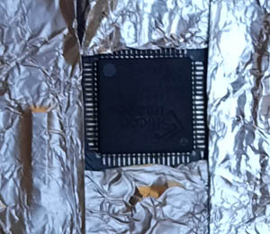
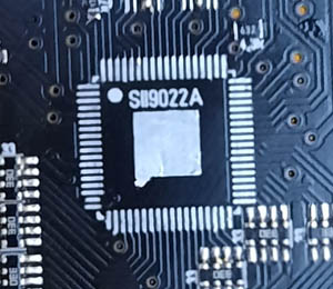 For desoldering I just placed some alu foil over the parts I do not want to desolder then just heat up with a hot air gun. On the right you can see the cleaned after desoldering... Next step is resolder. This time I solder the iC by hand printing the soldering paste on a PCB which is already soldered with other parts is not possible. Placing the iC and solder it by hand is even harder I recognised because you place the iC and then you grab up the soldering iron and pling it's shifted ;) But it worked after some trys... Solder such iC with 0,5 pitch is no problem you need for each side about 3-4 seconds. The trick is not to solder each pin individually. First you take solder to your soldering iron. Place it correctly and try to solder by shifting around the iron at one side. important is just the iC can not shift anymore. Then take some flux (I'm using Amtech nc-559) place it on the side (not the side you solder to fix it of course) you want to solder take some solder to the soldering iron and just shift the soldering iron back and forth this solders the side in a few seconds. You even do not need a small soldering tip. I use of all my solderings a 1,2mm one. important is just enough flux it does all the soldering As you can see on the upper right photo the iC has a ground place under the iC I put some soldering paste on it before I placed the iC. Of course I can't solder this by hand because it's under the iC. To solder this I put it again into the reflow oven... in the end it looks like this: 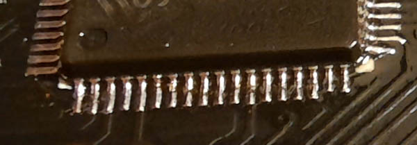
Have a nice weekend! ;) |
| 19.02.2021 ultraDev / HDMi Board |
My soldering output of the last 2 days: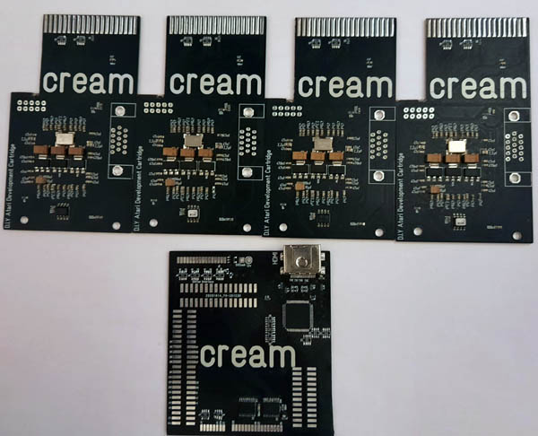 The @4 ultraDevs I need to solder the other side... On the lower my HDMi board I did. There I'm using for the first time this kind of smd chip: But it worked very well... 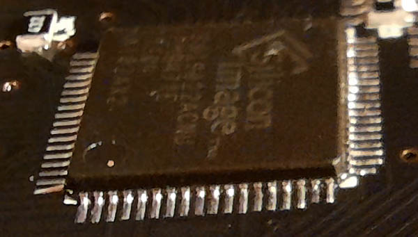 Unforunately I recognised after some time I soldered the chip wrongly by 180�... mh oh noes :( I just looked into the datasheet and saw pin 1 has a circle unforunately I didn't see there are two. lower left and upper right. the small circle is pin 1 ... bla To remove the short cuts on the HDMi chip I used this flux for the first time:  Cool stuff that worked really well esp. it's really easy to clean. Before I used rosin flux (it's hard yellow stuff) and extremly sticky and really hard to remove from the PCB. Also the solder flows alot better... That's nice ... |
| 17.02.2021 ultraDev |
While I was waiting for a PS5 drop yesterday I gave the new soldering paste another try and build up the back side of a ultraDev cartridge. Very strange this time it worked alot better almost perfect. I build now a frame for the stencil printing. Looks like this: 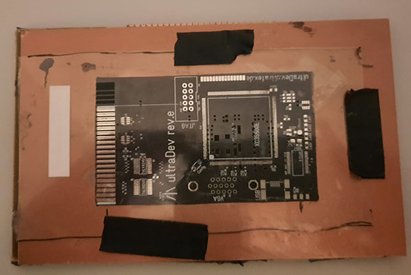 it's just an old PCB with a hole. The problem I had before was heigh differences of the frame to the PCB. if the heigh isn't 100% correct the solderprint does not work very well it smears and stuff if you have a look to my previous frame: 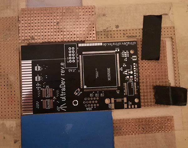 As you can see is an extrem improvement ;) Pretty nice the soldering paste is working better now so I can build up some ultraDev devices today... As you can see it has been pretty cold in germany ;):  |
| 17.02.2021 ultraTos |
Still no news from the ram chips for ultraTos. The seller is on holidays because of the chinese new year. Means earliest date for resending the ram chips would be 18.02 but I expect more 20.02 + 4 weeks shipping time so I'll have the chips maybe 20.03. Oh man what a shit... |
| 16.02.2021 ultraLA |
Today I'm a bit in brainstorming mood ;) ultraLA - LA stands for logic analyzer maybe something I'll do as a small side project. But first I need to double check if I'm able to do it with my possibilities (hardware wise) to fit my needs. During the ultraTos project I had a bug I was not able to trace down without a LA. I could fix it with my osc which is able to record 2 channels but well two channels is a bit less. The problem in ultraTos was in the SPi communication and there you need at least 3 so I have to record it more than once. There are quite some cheap LAs available on eBay. But if you have a closer look to the specs mh well 24mhz record speed. According to frequency theorem you are able to record values with max. 12mhz. Hm well what a toy;) if you want something more serious it's getting really expensive. So my questions for a LA are:
I think SDRam is the way to go. Using blockram or static ram is too less memory... it would be possible to use PC memory bars but just the standard SDRam no DDR. DDR would be possible and even better but well never used DDR ram until now. Hm but that would need quite some time to get into the bars specs and stuff. Better to start no endless project I'll use my SDRams I have. I have 32 mb chips here. if I stack them with separate ce signals I could easily increase it to 32, 64 or even 96 mb. How fast can it sample the channels?: The problem with the sample frequnce is of course not the sample itself more how fast can you write back the sampled data. SDRam has always a small overhead to activate/deactivate banks and refresh the ram but it's possible to write a value each clock. You can write with that SDRam I have up to 1024 values then you must change the bank. My idea is the SDRam runs with a faster clock than the record task. This will eleminate the overhead. Let's calculate a bit with a SDRam which runs at 145mhz which max sample frequnce it would be. 145 mhz ~6,89ns per cycle. Writing a page with 1024 values to the SDRam will need: 15 cycles bank activate and deactivate (it's less just for savety) 1024 cycles write page 10 cycles refresh (70ns/6,89ns) ------- 1059 cycles cycles * (1/mhz)*1000 = 1059 * (1/145)*1000 = ~7303,45ns need time to calculate the max sample frequence: mhz = 1/ns *1000 *cycles = 1/7303,45 * 1000 * 1024 = ~140,20mhz So the max sample frequence would be 140mhz. Of course it would be possible to double the memory band width this would also double the possible sample speed because write back of the data is faster. This is for 16bit means 16 channels. 8 Channels would half the data amount means doubles the possible sample frequence. Doubleling the 140mhz to 280mhz will be hard to realise maybe double data rate iOs would be an option. 32 channels would half the possible sample frequence anyway... So count of the channels must be changable. How many lines are needed or possible? Of course as many as possible. 32 would be nice but this also depends on the pin counts on the FPGA. Let's see: The FPGA has 116 free iOs. Needed iOs: 39 SDRam 12 USB ------- 51 So 51 would be possible but does not make much sense I guess and like above more channels will slow down the sample frequence. How to protect the FPGA before overvoltage? Have to investigate a bit. First idea was to use a 74lvc245 bus driver. it's able to handle 5v and in a case of an overvoltage it hopefully dies instead of the FPGA. And I'm not sure if 74lvc245 can handle to frequencies. Have to study the datasheet a bit. Which triggers are needed? Hm not used alot LA until now ;) For easyness 1 trigger with different trigger types like:
How to get the data on PC? and how to display it? Via USB. if the memory is about let's say 64mb and about 900kb/s transfer speed it will take >72seconds to get the entire memory. Hm that's not impressive. Maybe USB 3.0 makes more sense. How to display the stuff...? Displaying it via vga and FPGA itself is too complex it would need a GUi...I found a nice tool to display logic signals on PC... GTKWave: 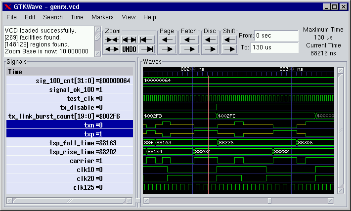 it can read VCD-files which can be generated easily. Another alternative would be the Xilinx iSim. it also can read VCD-files. How to reduce data? I mean this is an perfect example of using run length encoding (RLE) compression. The idea is to compress values inside one page (1024 values). Of course RLE will create a small overhead of the values but the win is alot bigger. The RLE commands will be 16 bit means with a 140mhz signal and 64mb and nothing changes it can record eh moment: 32767 values for one repeat chunk to express this it needs two values ->512 repeat chunks per page. 64mb = 65536 pages * 512 =33554432* 32767 = 1099478073344 values * 7,14ns = 7850273443676,16ns = 7850,2s -> 130 minutes -> 2,18 hours. Ok sure this is a theoretical recording time... Worst chase every value is different... 1023 values per page... 64 mb = 65536 pages *1023 = 67043328 values * 7,14ns = 489ms I guess this is oki with help of triggers and reducing the sample frequence it's possible to increase that time. How to do a LA with less development time? Creating a new PCB need too much time. I could use my FPGA board I did some time ago which has SDRam. 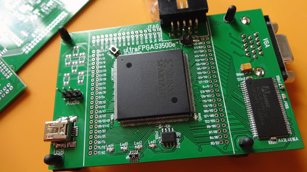 But I would need something for the channels including the overvoltage protection... Funny... during cleanup I found today an unfinished ultraDev PCB of an old revision. 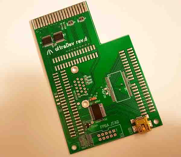 This is excatly what I need. The upper two ics are 74lvc245 for overvoltage protection. Also I can plugin the FPGA board to this board. Perfect. So I do not need to create a PCB. Ok this would limited to 16 channels but anyway could be extended to 32 with a small addon board or so. For the software I could use alot code of ultraDev like USB communication on FPGA and command line tool. Conclusion: Doing a LA isn't that much work if it has max. 16 channels. it would be possible with 8 channel to sample up to 140mhz that sounds pretty usable. Big advantage is that I do not need to code the displayer for the data. That would have been a k.o. criteria. I know everyone has fallen asleep already...anyway ;) |
| 16.02.2021 ultraTos |
Hm it's not going very well currently. Unforunately the seller for the ram chips did not send the chip until now meh. Seems my soldering iron slowly starts to give up meh... Started two ultraTos PCB yesterday: 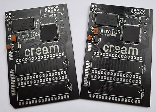 Unforunately the solder paste is somehow not that good. it's by far to liquid so a clean print is nearly impossible meh. So I had to remove alot of short cuts after reflow. With a slowys dying soldering iron no easy task. I hope the new heating element of the soldering iron will arrive soon. Unforunately I could not finish the PCBs I need jumpers for the boot selector and the pins for the Eproms I do not have meh besides there are 6 other orders on the way to me which did not arrive yet they should be here since one week. Seems the shipping from China is currently extremly slow. Maybe I'll do a small project switch today due to dying soldering iron and missing parts I even can't build up some ultraDevs meh ;) |
| 15.02.2021 ultraTos |
I created a new revision of the PCB yesterday. The first revision had two small bugs nothing big but that have been fixed. I started to write a manual for ultraTos mh not a very exciting task to be honest :) I'm a bit surprised about the resonace of the ultraTos project. I didn't expect this. The first batch was already sold out after 2 days. The second batch is almost sold out unbelievable... This means build up for ultraTos will need some time. Also I have a waiting list for ultraDev which I slowly start to deliver now. The ultraDev waitlist has a higher priority because the ppl are waiting alot longer for the cartridge. So today I'll build up two ultraTos PCBs for ggn and tin... Unforunately I can't finish them fully because I ordered some parts for it I hope they arrive later this week. |
| 12.02.2021 ultraTos |
Unforunately my cold came back :/ But shortly before I could finish the boot tool for ultraTos. So from my side ultraTos is done so far. I'm using it now since hm I guess 3 weeks and booting the Tos and working with it works without problems. So next step is to send tin and ggn and let's see how it works out there. Unforunately I can't build up new PCBs currently I do not have ram chips anymore. I Hope they arrive soon... What to do next? I think I'll build up some more ultraDev in the next days. I think I'll start roll out soon. The last release was pretty stable no problems so far. I used it alot during development of ultraTos. Unforunately I already contacted 3 ppl and no of them reacted since weeks. This is great... I mean if they don't want it it's just one line to send. This slows down the entire process because I will deliver one at time and jump to the next if the guy is satisfied...Means I'll deleted the preorders now. if they still one contact me... But anyway there are some left I'll contact them in the next days... |
| 08.02.2021 ultraTos |
Coded today the flash tool for ultraTos on Atari. Works pretty well flashing a new Tos needs about 8 seconds. it's also possible to erase a Tos. Tos 1.x is also supported. I'm using RamTos to relocate the 1.x Tos to STE Tos Rom space. So ultraTos is close to be finished just some small prg files which enables booting into a new Tos from Desktop and that's it. Nice and small project I always wanted to have... |
| 05.02.2021 ultraTos / ultraDev |
Finally I almost recovered from my heavy cold. 8 days of doing nothing was really great... anyway I could fix the bugs in ultraTos. Now I'm able to flash Toses from Atari which is pretty cool. I also can boot into different Tos-versions during runtime. So I added support to ultraDev means some additional informations are now shown which Tos is running also ultraDev detects now an installed ultraTos. With installed ultraTos you can show the different flashed Tos-versions in the ultraDev cartridge screen and you can directly boot into a selected Tos. This task needs just a second. Small video which demonstrates the Tos switching: What I'm doing in the video is. First show the flashed Tos-versions next switching the Tos by clicking the keys. After the Tos is loaded it resets and the Tos is active. The current running Tos you can see on the upper right. At the beginning you can see the ultraTos PCB installed to a 1040STE no additional cables are needed. That cables you can see in the video is just a power supply cable to power up without STE to test stuff and a JTAG cable to program the CPLD. I added a new video mode to the ultraDev VGA screen. Now it's possible to display 80x25 chars on screen. Looks like this: 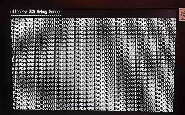 Quite a productive day. That's it for today need to rest a bit ;) |
| 28.01.2021 ultraTos |
This week was not very productive until now. I was searching some nasty bugs which did not appear in simulation. A logic analyzer would have been really nice to trace down the problems. in a FPGA project you have the possibility to include a minimal logic analyzer (ChipScope) into your design. With ChipScope you can scan output pins on the FPGA. it's quite limited but helps mostly. I used that in ultraDev to check the correct timing of the cartridge bus. Unforunately ultraTos uses a CPLD and ChipScope is not possible on that device. I was already searching on ebay for a logic analyzer then I had the idea mh I can record stuff with my oscilloscope (never used this until now). Unforunately I can only record two signals. The SPi EEProm has 4 signals (select, clock, in and out). Luckily the oscilloscope has an additional trigger line. This can be used to start recording. Of course I can't record record in and out at the same time but anyway that was enough to debug. The first problem (busy signal was not set from the EEProm) I could fix quite fast. The second was really nasty and tbh really embarrassing ;) So how is it possible to access the EEProms over a read only address space?. The roms sockets even do not have a read/write signal? To write to such a bus is possible by reading from specifics adresses. For example sending a value to the SPi EEProms: The 1040STE rom is placed at address $e00000. if you want to write a value of $87 to the CPLD you can do this by reading from move $e00000+($587<<1),d0 The CPLD recognises an access to $e00000 because of the rom select signal is low. 5 means here write the value $87 to the SPi EEprom. Reading from the SPi EEProm works very likely: move $e00000+($100<<1),d0 read from spi move $e00000+($101<<1),d0 get the previous value from the spi read Two instructions are needed because the first instruction reads from the EEProm and this takes longer because reading and writing to the SPi is serial based. But this works only if you: a) after move #$2700,sr to disable all irqs b) the CPLD must be in a special mode to ensure the normal execution from the Tos is working fine and not sending any data to the SPi EEProms. I'm entering the special mode inside the CPLD by reading 10 times on a specific address means 10 accesses to $e00000+($dead<<1) will enter so called SPi bridge mode. The accesses must be in a row as soon as a different address from rom space is access it resets the counter. it's pretty unlikely that happens in normal operation. Only in this mode it's possible to access the SPi EEproms directly. A really nice bug I had was when I started to flash the roms hm what should flash to the rom? Ah well just use the original Tos means I was reading from $e00000. Unforunately I totally forgot I'm in the bridge mode ;) Means when I read out the Tos it sent data to the SPi EEProms. Great idea... That I only recognised when analysing the SPi communication... bla Flashing does not work fully currently there is a small bug I'll trace down in the next days. But loading the Tos from the SPi EEproms and working with it is very stable I did not have one crash the entire week which is really nice. |
| 20.01.2021 ultraTos |
A few days ago my new PCBs arrived:
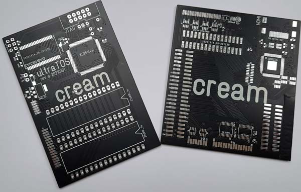 On the left is the Tos switcher on the right the Hdmi PCB. Currently I'm working on the Tos switcher. ultraTos I already build up and seems to work so far at least the hardware (CPLD, ram accesses and EEProm access are working). Except of only one small mistake forgot a track but that was no big deal. Currently I'm trying to get it to run but doesn't work yet. First problem I was fighting with was how to programm the EEProm for the Tos? Well the EEProms should be flashed from Atari but without a programmed EEProm I can't boot the Atari ;) I knew about the problem when I designed the PCB so I added some pads to programm the EEProm directly with my Xilinx programmer. That was the plan but of course this didn't work ;) Years ago impact (software for the Xilinx programmer) offered a feature to directly programm SPi EEProms. Unforunately they skipped support for writing SPi EEProms in impact in newer versions of impact. Great job Xilinx... So I reactivated an old computer from my girlfriend with Windows XP because of course the old version of impact doesn't install on Windows 10... Great job Xilinx. After installing the old version I saw yes you can program a SPi EEProm but they need a special file format for this and the file format I don't know... hm Great job Xilinx So I had a sexy looking PCB where I currently can't programm the SPi EEProm great that was a good reason to open up a beer and switch off the computer. Next morning during a shower (I have my best ideas there dunno why ;)) I had the idea hm ultraDev is using the same SPi EEProm for the FPGA configuration data. What about just copy the FPGA project and modify the firmware a bit to use different pins and then connect ultraDev to the ultraTos PCB? And yay that worked. So I have a SPi EEProm now which holds a Tos puh that was a real pain in the ass Currently I'm trying to read the Tos from the EEProm into the ram but somewhere there is a bug I didn't find yet. if I check the first word which should be $602e (or so) that doesn't fit what I read. Hm odd... Anyway I'll trace down later... |
| 12.01.2021 ultraDev |
New release is out and tested with the new half automated test script. Man I should have done this alot earlier. it's so much time saving... I have round about 20 test cases in the script now. it's just a question of maybe 5 minutes to test all features. Also nice to test if a cartridge is working fine after build up... My todo list is so far empty and I'll not include new features. Maybe a good idea to build up some more ultraDevs ;) I sent one cartridge to wietze he is a mac user maybe he can play a bit with it... So let's see how the mac stuff is working. Tracking says my ordered PCB's should arrive maybe tomorrow...yay |
| 10.01.2021 ultraDev |
During my development sessions I recognised it's extremly stressy when you debug with bugaboo you always need to change to the Atari keyboard to type in stuff to debug. Hm that can be done better ;) I included a keyboard mode to the command line tool and Bugaboo. in the keyboard mode the command line tool does not exit after starting Bugaboo and loading the prg file to debug. All keys from the cmd window on pc are send to the cartridge. The modified Bugaboo version reads the keys from pc and outputs them to the bugaboo screen. Very handy. Makes debugging alot easier. Another feature I added was the support of multiple ultraDev cartridges connected to the host computer. Added support for the Rpi and Mac build in my make release script. Well without that make script I would surely get mad. Building a release is unbelievable much of work there are so many task to do like: building the command line tools for Windows/Mac/Rpi, build font rom, build 68k firmware, build the 68k firmware coe, build 68k rom for the FPGA, build FPGA for PCB 1.0 and 1.1, create the programming files for FPGA for 1.0/1.1 and finally create the release directory and zip. This is pretty cool so I just double click on a bat file and everything is build... Today I started a half automated test script which tests every feature of ultraDev to ensure the software quality of a new release. Well I'm a lazy ass testing I do not like very much and often you forget something to test. Not fully done but looks really promising... During the week in build up some ultraDevs: 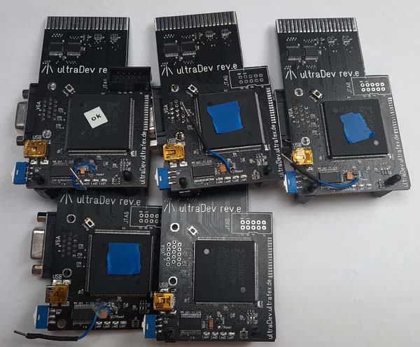 Not all are fully tested yet. The one with the blue sticker are basically working but didn't pass the long time test. Every cartridge I'll deliver is tests about a day during development. Also the manual has been updated... Man I hate that... Quite a productive week. A new release is already prepared just need to test it. Good reason to improve the half automated test script ;) |
| 03.01.2021 ultraDev ultraTos |
I the last days I had a longer demo coding session with ultraDev mh can't remember when I did this for the last time... The last release is working pretty stable also no bug reports from the beta tests yet... Checking the PCBs (Tos switcher and HDMi) for manufacture is done and the PCB are already produced. I guess I will get them in the next weeks. Unforunately I did a small mistake with the TOS switcher. After I gave the layouts to the manufacturer I recognised the bigger CPLD I planned to use isn't available in 100pins version. Hm that's bad and a small panic mode came up... So I started to implement the Tos switcher verilog code. in simlation it works so far but what really wanted to know if it fits into the smaller CPLD. Loading the Tos into the ram seems to fit. The first code for flashing showed it will not fit into the device... Hm shit... Writing the flash pages and all other handling was too big for the device. Hm how to fix that?. After some time I had the idea. When I enter the flash mode why not open a direct channel to the flash and let the Atari do the flash handling? That seems to work. So now I can read and write diretly bytes directly from Atari to the flash memory. There is even space to do a Tos boot selector for the Atari means you just double click a Prg file on your Atari and the Atari boots up the Tos on the following reset. That's nice... Ok all is working in theory let's see how this works out when the PCB arrived ;) |
| 23.12.2020 ultraDev ultraTos FPGA board |
Had been a bit quite in the last days was a bit lazy to update the page. I had a one week without internet and tv vacation some kind of digital detox ;) Before the detox I did a new version which had unforunately two stupid bugs so I had to create a new release yesterday. Hope this works out fine. During testing I recognise from time to time I really need to test on different Tos versions. Unforunately I do not have a eprom burner running. That old one I have do not work on Windows 10 anymore... So I've decided to create a small PCB and looks like this: 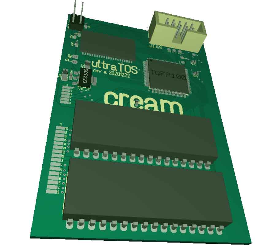 This is a Tos switcher for Atari 1040 STE. it will have the possibility to hold 6 Tos versions which are switchable by jumpers. in the first step the Tos verions are only flashable with a Xilinx programmer to minimize the development time. Later it will be possible to flash the Tos version directly from the Atari. How does it work? The card has 256kb of ram, 3 Spi proms and a CPLD (small brother of a FPGA). After a switch on the CPLD loads the Tos from the Spi prom into the ram. During Tos loading every access to the Tos rom the CPLD will output a $60fe which is a bra.s *-2 which holds the 68k in a wait state. When the load process is done it finally resets the Atari. The project will be open source means I'll release the PCB layout, schematics and source for it. Normally I'm a fan of doing the PCB here at home but the PCB has about 80 vias which is a pain in the ass to do. So I've decided to let the PCB create by a PCB manufactor together with the HDMi board I posted below. That saves time. So today will be a heavy PCB checking day. |
| 09.12.2020 Keyboard Fix |
Finally my vacation started that was really needed. Yesterday I did something which I was shifting since a year or so. Finally I had some time to fix my 1040STE keyboard. Before I was using a 520ST keyboard which has no mouse/joystick connectors. The keyboard got short cutted my the power supply and well there was quite a bit broken diodes, resistors, iKBD, 74ls244 but I could fix that. And it's working fine again. Next problem was I do not have a Atari mouse but an Amiga one. So I soldered a small converter cable. So I finally have a Atari mouse this is really awesome! Before I always had to use the keyboard to move the mouse. Luxurious ;) So what do we learn about this? Always remove the power supply if your Atari is open the entire time. My power supply is now extern. Besides alot more save for yourself too... |
| 24.11.2020 ultraDev |
The problems with the Mac port of the command line tool are fix. Also folder share is working fine on Mac OSX and Raspberry Pi...Niceness I'm really happy that the port to unix was that "easy". During development I already had in mind... guy you will possibly port that code to unix that helped alot... Really great was during development I was done and wanted to rebuild again with a make clean on both plattforms. And? Due to a great bug in my makefile it deleted the sources instead of the object files. Of course I didn't checked in to git before. This was really great. Back to start and redo all of the shit... Ok rest of the week will be testing time. Got really alot to test before next release... |
| 24.11.2020 ultraDev |
Started yesterday the port of the command line tool to Raspberry and Mac. On Raspberry I can already upload prgs to the cartridge which is really cool. Unforunately is Mac a bitch like always. There is a int and long mix up in the source which forces the Mac port not to work. No big deal to change this I'll do later. But the port needs some more work for the folder share thing. Scanning the directory works different on Unix but I'm optimistic this is a bit of work but nothing impossible to change. I'm already happy I can compile and link the command line tool on Raspberry and Mac and esp. The libraries for the USB driver are working. |
| 20.11.2020 ultraDev / FPGA board |
Added some new features and removed bugs in ultraDev today. So what I wanted to add to the release is included but need to test a bit more this time. Well there have been quite some changes to the folder share thing. Hope all is working fine... To have a better video output esp. more colors for my SDRam stuff I started to develop a new addon for my FPGA board. Looks like this: 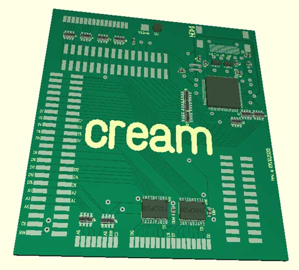 I started this some monthes ago and worked from time to time on it. I think I'll try to do the PCB next week if the last check of all connections is successful. With a Spartan 6 FPGA you can do a direct HDMi output I was thinking about maybe to change to Spartan 6 (currently using Spartan 3) but well for higher resolutions you need a really high clock which is beyond the possibilities of the Spartan 6. So I've deviced to use my old chip and using a external HDMi chip for that. When zerkman got this FPGA board for his Atari in a chip project he told me it has a SiL9022 HDMi chip on board. Well after checking the datasheets I've decided to use this too. Also good if you know someone who got it already working ;) Btw. you should have a look to zermans site: Building an Atari ST Really interesting stuff about this project. The sil9022 chip is quite small 1cm x 1cm 0,5mm pitch of pins. Looks like this: As you can see the chip has no real pins. The pins are more or less placed under the chip. Hm not sure if this works fine with my reflow soldering. I mean if you can place the chip perfectly it will work but placing by had a 1x1 cm chip with 0,5mm pitch is a challenge... But let's see... |
| 17.11.2020 FPGA board |
in the last days I continued the SDRam experiments. Means I tested my new SDRam controller on real hardware. This is the result: Seems I understood SDRam now...;) But still using SDRam is a real pain in the ass... I thought displaying a picture is boring also this is not what I wanted to test. So I had the idea why not code a small rotzoomer a good test for random access to SDRam. The rotzoomer uses that technique I descripted below in my last post by using two banks to speed up read accesses. The texture is at startup in block ram from the FPGA and copied to SDRam before the effect starts. The rotzoomer runs in 640*1024 at 60hz. The resolution is normally 1280*1024 but doing a 1280*1024 rotzoomer the SDRam is too slow. I'm pretty happy the SDRam controller works that good. When I coded the effect I didn't do a change to the SDRam controller. This is cool and shows a) simlation rocks and b) the simlation model for the SDRam chip is pretty precise. And even cooler the FPGA board works fine even under stress... I really love to create stuff on VGA displays. This is really fun. When I remember back to my first hardware steps back in 2005... Really retarded compared to the rotzoomer. But anyway I was really new and at this time I was really happy I could create a VGA output ;) 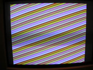 This was my first VGA output I ever did. Created by this: 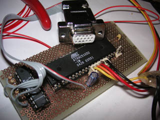 A 8 bit cpu unforunately the resolution was that low 108*500 so I did not continue here. The selection of the cpu back then was a big mistake it had 60mhz but it needed 12 cycles for every instruction and well. But anyway Over the years I changed to pic32 with 80Mhz and I started with programmable logic on CPLDs. in 2010 I did this: Hardware for this: 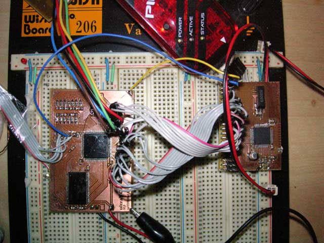 This was alot more advanced than the first VGA test. And it was alot more work to get this to run... This was the first time I used programmable logic and as a c/asm programmer this was real nightmare to get into. it took monthes... On the left the VGA graphics card. it has a CPLD to receive the writes to the screen from the CPU and some SRam. On the right the pic32 cpu. Originally I planned to code a demo on the pic32 with that hardware but guess it ;) Like in good old tradition it never got finished ;) Yeah and right this is the head of sono ;) Ok the rotzoomer doesn't look that impressive like the old pic32 thing. But it is alot more advanced and besides it does not use a cpu... So SDRam experiments are done now time to get back to ultraDev... |
| 13.11.2020 FPGA board |
Still working on the SDRam controller for my FPGA board. Well for a beginner this is really challenging or better... Doing a simple one is easy but to have a good performance isn't that easy. Reading blocks (bursts) can be done very easy and fast but the problem is to do random accesses over different rows. Some example to illustrate reading from SDRAM: actA/B Activates a bank from the SDRam rdA/B Read from the bank. datA/B Data available ---- Nop cycles All examples are with a latency of 2 clocks. This means depending on your clock speed the ram needs 2 cycles or 3 cycles to execute a specific command. The times are fixed if you have a higher clock speed you need to add wait cycles. Reading a block of 4 memory values via burst looks like this (each part is one cycle): actA ---- rdA rdA rdA rdA ---- ---- ---- Makes 9 cycles for 4 memory values. if you read for example a full page of memory values (size depends on the chip mostly 256-1024 values or so) it's getting really fast. The 3 cycles at the end is needed to precharge the row. Precharge means you close the row and the capacitors of that row are charged with the correct values. A random access to a row reading one memory value: actA ---- rdA ---- datA ---- ---- ---- So reading from one bank it needs 8 cylces. Pretty slow mh? But there is a way to speed it up. My SDRam chip can open two banks at once. As you can see in the upper access there are quite a few nop cycles. if you place the same data on different banks sure wastes a bit of memory ;) But this is maybe interesting if you have a texture in SDRAM. An access over more than one bank would look like this: actA ---- actB rdA rdB datA datB To access 2 memory values on different banks need 7 cycles. Quite a speed up to 2*8. As you can see the 3 cycles for precharging the row is missing... Why? it's not needed here bank a is already precharged inside the access bank b will be precharged till the next read is started. That's pretty cool. if you do not want to waste memory you can spread your data over the banks. Means for example odd address memory values bank A even address memory values bank B. This reduces of course the speed a bit. Depending if you read two odd memory values you would need 8*2 cycles if you read odd / even you would need 7. Another idea to speed up. Well the SDRam chips are really cheap I paid 0.23Cent for a chip. You could solder 2 chips back to back except of the CS pin which will have an own signal from the FPGA. So you have two SDRam chips with different CS signals. Writing would be done to both chips at the same time (means both cs signals are low ) but reading not. A read cycle would looke like this: 1 = CS signal for chip 0 and 2 for the second chip: act1 act2 rd1 rd2 dat1 dat2 So a random access with two values needs 6 cycles. As you can see the nop cycle is gone between actA and actB. This nop cycle is needed normally when you activate a second bank on the same chip. I think I'll go for the first try with only one chip. I what I'm planning to do it's fast enough with 7 cycles for 2 random accesses. Till now I only did a simulation of the entire SDRam controller hm I hope this works on real hardware. But I'm optimistic the simlation model from the SDRam chip is pretty good... |
| 06.11.2020 ultraDev |
Time was a bit limited this week but I build two new cartridges. One is done and working fine and the other one the FPGA side needs to be soldered. I've decided to build up some cartridges in advance so I can test them during development. No new bugs from the beta testers so I'll do a new release next week. So... time for some SDRam experiments ;) |
| 29.10.2020 ultraDev |
The new mechanism to load from PC during a folder share is now save implemented. Transferrate is still about 810kb/s with my setup... Beside this I did quite a few bugfixes in the folder share biggest fix was the file count in sub directories. Before the folder share was only able to hold files in a directory which fit into one sector. Now it's extended. Luckily tin and me could trace down the incompatiblity with hddriver. I'll include a small fix and then I will do a release...Todo list is getting smaller ;) |
| 27.10.2020 ultraDev |
I could finish the new release today. Let's see how this works out... Beside this I had a look how to speed up the transferrate for the folder share feature. Currently it can transfer about 580kb/s. Then I had the idea when I send a sector why should the Atari wait till the full sector is received via USB? The Atari could start to copy the sector even if it is not fully received. I'm doing this already if you start with the normal prg start feature but just didn't thought of it to use it here too... Tried it out and now I have a transferrate of about 810kb/s this is round about 40% faster... Holy shit ;) But need to do a bit more save if the second half does not come in time it could copy crap did not happen yet but anyway. Just a small addon... Of course I tried Drone after that fix. Drone is now working without a fix... Niceness!! |
| 27.10.2020 FPGA Board |
Yesterday I was working on my SDRam controller. Puh not that easy luckily I found a good simulation model for SDRam from micron. it's not fully the same but it was possible to make it fit esp. changing how much memory the controller has and even more important are the electrical characteristics like cycle times and delays. Without that SDRam simlation model it would have been a mess to test the SDRam controller on real hardware. I mean understanding how the SDRam works how to read data from it is one thing but there are so many small things you have to consider. Of course if you select data during a read that it has a latency till the data is available is clear but you need to add delays where is it not so clear in the first glance. Luckily the SDRam model checks all this and the SDRam controll is working fine currently with read and write bursts. Almost 600 lines of code just for this and I'm not done yet for that what I need. But now I see why a SDRam controller is hard to find for free. Some are available but often something is missing, unflexible or they are buggy... What I need to add are the refresh cycles but I've decided not to include automatically means the SDRam controller does not recognises a refresh cylce is needed you have to initiate by yourself. I think this is easier in the first try... So today will be an ultraDev day... hope to finish the new release soon... |
| 23.10.2020 ultraDev/ FPGA Board |
Had a look to Drone today again. I could fix it to run 100% on ultraDev just by changing a counter in the Vbl...nice ;) Today I started to write a SDRam controller for my FPGA board. Works pretty well so far. But I've started to code the controller with simlation first. Well a SDRam controller is a bit more complex than the normal ultraDev stuff where I normally do not use a simulator. For those how aren't very in FPGA things. The simlator simulates the code you do hm very unexpecting ;) it helps you what's going on in your FPGA. Well on a FPGA debugging isn't that easy like in C or assembly. You can output signals to the pads which you can grab with Chipscope but you can't see the internal signals. So simulation is a important task during bigger FPGA developements. The output of a simulator looks like this: 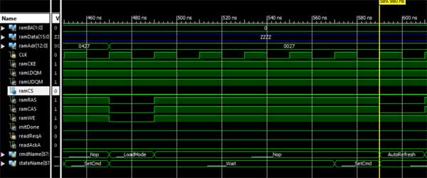 What you can see there a part of the init sequence for the SDRam. For the simlation you need a test source which sets the signals and values on the busses on a specific time. With the output you can check if the design reacts correctly... This time I used for the first time iSim which is included in the Xilinx ide maybe not perfect but works so far. Normally the standard simulator is ModelSim but the GUi is the pain in the ass and the license for free is only valid for 180 day then you need to renew it. One reason I seldom simlate the design. The SDRam controller can only init the ram currently just started to code the read sequence but that I'll continue tomorrow... enough for today... |
| 21.10.2020 ultraDev |
Oh man. The last two days have been really terrible... I was searching a bug the entire time. Somehow the folder share did not work anymore something was wrong with usb communication. I was preparing the new firmware to be released. On monday everything was fine. Thuesday the folder share did not work anymore. I compared the sources 1000 times used usb sniffers and stuff and in the end I've decided to go back the old version (thx git ;)) and add all changed step by step. Hm it worked again but no idea why. This is as always a bad sign and will come back sooner or later. So started to finish the release and after some time it was not working again. Then I recognised when I change the version number to 0.53 the folder share did not work anymore...WTF After checking the FPGA source to read a sector I saw when the request is send it does not return to idleState instead it sends the version number nothing else. Well each of my data packets over USB start with SY. Sending the version number after request a sector is of course a bug but was never a problem till version 53 which is send in hex and 53 is S and S is the first byte of my sync word which causes the command line tool to run into a time out. WTF2 Uh I didn't have a bug like this for a long time I think I've got some more gray hairs in the last days... But I'm happy I found that already had nightmares about that;) Ok back to testing again but not for today. I'm fed up with ultraDev for today ;) A bit later.... mh damn I could not resist ;) One thing is nagging me... Drone from DHS is not working. So I tried to speed up or search possible reasons why it does not work... important for me is to know is it a driver problem or a bandwidth problem?. Unforunately I could not speed up but I've got Drone to run not 100% let's say 95% ;). Now I know it's a bandwidth problem in combination of not optimal code. Seems the demo demands stuff loaded at the very beginning correctly in time if it's not done it crashes. Could have been done better tbh. What I've done is to rename the file big.4pl (which seems to be the big drone logo) and replace it with a smaller file then the entire demo works fine till the end... That's nice one thing with less on my todo list ... |
| 20.10.2020 ultraDev |
Yesterday was a bug fixing day... I've got the first results from the beta testers. So a little testing and then a new release is done...
|
| 17.10.2020 FPGA Board |
So let's get into SDRam. I already read a bit of SDRam and well I always had alot of respect for using it which ended always in using SRam. I'll write a bit down here for later readings...No need to read this is very boring stuff ;) So why do I want to change to SDRam? SRam (static ram) are normally better for FPGA things if you have straight timings. You do not need to refresh and you can create a constant output stream for example for a VGA graphics display. The problem with SRam are:
SDRam is organised in banks, rows and colums(page).. When you read for example from SDRam you first need to activate a bank/row (you can activate up to two banks at the time) and then you can read inside the page by random access or with a burst read depending on the ram/mode its a 1 2 4 8 or fullpage burst each clock. When you want to access another row of the bank you need to close (precharge) it. Precharge means the capacitors of the row are charged which implies a refresh on that row. if you only need a part of the SDRam and you access the rows often enough you can skip the refresh cylces. if you need all of the ram you need to do 4096 refresh cycles in 64ms (with my chip). Means you can't use SDRam like SRam to create a constant stream output. For a constant stream output you need to read the data into internal FPGA memory and use that for output. in my first programmable logic experiments with CPLD's which do not have internal memory that was not possible. That's why I never used SDRam until now. Also creating a controller for SDRam is not so easy if you are a beginner... That's would I understood so far I hope I've got all correctly ;) So let's get some code done A bit later (ok took quite some time ;) ) I saw this on screen: 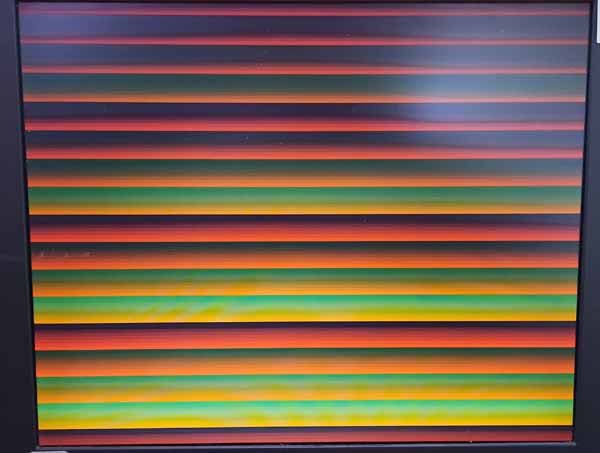 Can you imagine after I seeing this on my VGA screen I shout out a big YES!? ;) I guess not but this is the first usage of SDRam with my board. What I'm doing here is of course creating VGA signals and at the start of the code I'm writing 256 bytes to a page of the SDRam. This SDRam page I'm reading one word (it's a 16bit ram) out each line. Remembers me alot to my first raster lines on ST ok the raster haven't been that stable tbh ... Cool ;) Really nice is the read out works fine with 108MHZ (pixelclock for vga 1280x100@60hz) the ram could do 166Mhz have to check that later if it still works with that speed... For quite a while during development I had always a black screen. The ram was not talking to me nothing was outputted. That's a really stupid situation when you try to communicate to a chip and just nothing happens there are 1000's of possibilities what could be wrong. The problem was the ram wasn't initialised correctly. I misunderstood the power up sequence. And this seems to be really important to get the ram working. if you do not init the ram correctly the ram says "you sucker read the fucking manual" and ignores everything. So that's it for today I can start the weekend... weather is great so better to go outside ;) |
| 16.10.2020 FPGA Board |
Oki back to my earlier designed FPGA board.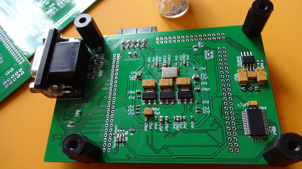 The FPGA board was designed for: a) ultraDev for this the left and right side of the PCB is cutted. The FPGA board was used for ultraDev rev.d b) for some more FPGA tests esp for my new FPGA Atari project. The FPGA board features are a 24bit dac, SDRam with 166Mhz, USB communication chip, VGA output with max. 512 colors, leds and some switches. Currently I only tested the if the board itself works means FPGA booting and so on more was not needed to use it for ultraDev. Next is now to see if the rest is working fine. I'm really curious how this all works out unforunately I had to wait quite a bit to test this because I did not want to start before the new release of ultraDev is done. First step will be now to output some on the fly created picture on VGA. Hopefully no big deal because I already did this quite often... ...a bit later Ok VGA seems to work...: 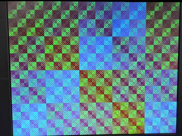 Next is the SDRam hm but this will need time I guess... |
|
14.10.2020
ultraDev
|
I could finish the new firmware version and it's installed on the cartridges from the beta testers now. YAY...
Let's see how this works out ;) During testing I'll do a small project switch and do some tests with my FPGA board esp. working with SDRam...Never did this till now but I'll need for my next Atari FPGA project... |
|
12.10.2020
ultraDev
|
Some time ago I started to create a bat file which recompiles all and creates a release. Creating a release is a pain in the ass if you do it with the GUi of the Xilinx tools and other things you need to do before. So many steps like creating the files (68k firmware or font rom) and create the config roms for PCB revision 1.0 and 1.1 that's too much to do it by hand... Unforunately the content of the 68k firmware was never up to date also the config prom file for the 1.0 PCB version did not work. Luckily I could trace that down today. About 10 hours of work bla. Just commit to Git and never have a look to that shit... Anyway so the new release is almost done now. On friday I tested already a bit and it looked good. So tomorrow I'll have final look... Oh almost forgot to update the manual.. Meh... |
|
09.10.2020
ultraDev
|
During my longer break I tested a bit debugging with Bugaboo. Unforunately it didn't work :/ That leeched again all my motivation because debugging with Bugaboo isn't that easy to realise. Normally you load the executable from disk and then you start. in case of ultraDev Bugaboo needs to load with the cartridge over USB and debugging this is a pain in the ass... Also loading of the symbols is working quite different and need some special handling. Means if something is not working here I mostly loose motivation and I could start puking immediately ;) Some time ago I've got a new version of Bugaboo from tin which assembles fine with vasm without that I would have skipped the Bugaboo support already. But it was still not working luckily I could fix the two bugs today. So just commit to Git and never have a look again to that part. The not working Bugaboo was the main reason why I didn't do a release yet. So I'll test a bit maybe I can do a new firmware release soon. |
|
07.10.2020
ultraDev
|
Ah well... Long time no update. I'm sorry. Unforunately private life leeched almost all of my spare time and motivation. it's not fully done yet but I hope I can do a little more on the project in future... You surely recognised the new PCB picture on the start-page. Shortly before I left to my short vacation to denmark in end of september I recognised... Hm I do not have many PCBs for the cartridge left. The question was just reorder the old PCBs again? Or should I do a new revision of the PCB? Well because of my perfectionism (which is really annoying sometimes... hm no tbh mostly;)) I've decided to create a new revision of the PCB. This is how it looks like upper and lower side: 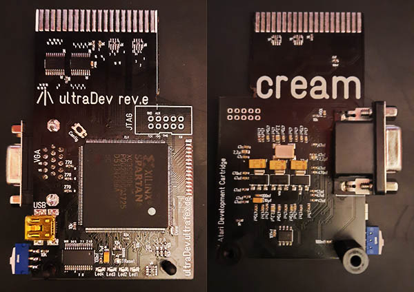 The advantages of the new revision:
All preorders will get the new revision and of course for the new price... I build up the first PCB today and it's working fine so far I could test. Which was pretty cool and motivating...I'm really happy the new revision works and it was so much easier to build up... So finally I have a test board again. I sent my dev board to tin some time ago because he ordered a second one and he was waiting really long and I had no time to ...do things... I'm fully working in home office since march for this I need a mac to do things for work. Which means I'm able to add mac support for the cartridge and maybe rpi. But this is no promise I'll see how much work it will be to port. |
|
21.07.2020
ultraDev
|
I think my solder problems are gone. I calibrated my reflow oven now and created a new temperature curve and seems that works again. Finished 2 cartridges for ggn and sent it over. tin's is done too but needs some testing. To get the FPGA board to run was a real nightmare. There was always a short cut I could not find. in the end it was a short cut under a capacitor and I checked the entire time the FPGA pins meeeh. Rest of last week I spent on integrating tin/ggn's Bugaboo into the new firmware. Luckily they patched the Bugaboo to run on Falcon but most amazing feature it assembles now with VAsm before I always had to use Turboass to make changes to Bugaboo meh... To get Bugaboo run again with the new firmware was let's call it a >>real pain<< in the ass. Not the new source of Bugaboo more it really changed alot since I tried Bugaboo for the last time. it was not working for quite a while but I was too lazy to trace down ;). Unforunately it was not only one problem anyway. it's working again that was a big step into a new firmware release. So I'll test a bit and esp. the new folder share feature. Beside I included a small new feature. Normally the commandline tool resets the atari by default before it loads a prg file. Now it recognises if the cartridge screen is up and if so it does not reset the atari anymore. Saves a sometimes a reset. I recognised when I use ultraDev to watch demos it's always stressy to start it in the command line. This is why there is a little small feature now ;) You just can drag and drop a prg file to the ultraDev.exe and it starts it automatically without command line typing stress. This is very handy for demo watching sessions... also nice for testing... |
|
09.07.2020
ultraDev
|
Unforunately less time this week. Having a bigger release currently at work. But I could trace down all problems from the first 2 cartridges and they are working fine now. The test board was a real help here. I'll test a bit in the next days and send it over to ggn... I did some research why the soldering was that bad for the first two FPGA board I build up some time ago. it seems the old soldering paste needed alot less temperature than the new one. I think I need to calibrate the soldering oven better esp. before I build up the FPGA board for tin. Today I've got a thermocouple for my digital multimeter. it's able to measure up to 1000�c. Hopefully I can calibrate the oven alot better than before... |
|
03.07.2020
ultraDev
|
Over the week I could finish the test board and coded a small firmware which toggles all leds Looks like this: 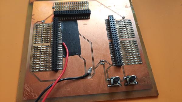 No beauty I know ;) I recognised during reflow of this PCB that something is different with the new soldering paste. it doesn't solder at the same temperature like the old one did. Really odd because it's the same also same manufacturer. Well maybe it's because it's from china ;) After I saw the PCB is not soldered correctly I redid it again with higher temperature seems it was a little too hot anyway but does it's job. Placing 232 0603 components is no fun ;) it's really nice to have such thing helps alot to trace down problems... Seems that was the problem with the FPGA boards the soldering paste was not soldered fully have to do more test reflows now... Also I recognised one FPGA board the oscillator was broken. So after replacing all FPGA boards are working now. |
|
01.07.2020
ultraDev
|
Ah well... Last day of my vacation and I didn't manage something really to get working. The FPGA boards I started not working 100%. I can upload a design but there are some pins not connected.it's expremly annyoing to see/check which are not not connected. I can't see a problem with the magnifier somehow. So I've decided to build a small test PCB to check the pins. 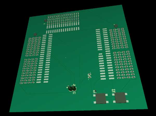 Hope this makes it a bit easier to find out which pins. Really odd why this happened maybe it's the new soldering paste? Have to do some more tests. But at least I could trace down a strange behavoir. I often had the problem when I upload small PRG-files that the PRG-file isn't executed. So today I'll do the new test PCB so far my migraine from yesterday does not come back and the leds arrive today. |
|
28.06.2020
ultraDev
|
Back from vacation. Have been really nice in .dk great weather and really relaxing after that corona crap anyway. Due to my experiments my STE is always opened up. Some time ago I extracted the power supply to external so I can use the STE without 220v nearby. 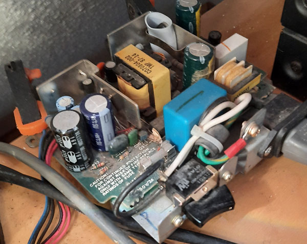 Yups a bit dusty anyway ;) Yeah that's alot better. in the beginning of my experiments I blew up my STE keyboard because it had contact to the power supply. Hmm that sucked really. So I searched a ST to use the keyboard in my STE. That worked so far after a small connector converter. Yesterday I remembered that ST. Hm Maybe it's working? Never tried. it was sold as broken because of a missing power supply. Maybe I can use the STE power supply to start the 520ST? The power connector from the STE looks like this. 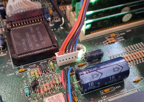 A short compare showed hm -12v is missing. I remembered I read somewhere -12v is only needed to serial and TV modulator mh. Let's try;) Due to the missing power supply connector for the 520ST I soldered it directly to the 520ST PCB. Lower is the 520ST upper the rest of the STE. 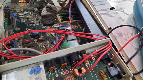 And? Tataaa 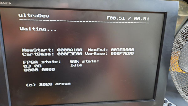 The ST boots up with the ultraDev cartridge. Nice. it has even 1MB of ram. So buying it for 12euro was really cheap. Cool ;) This is actually really nice so I have a second ST to test also with a different memory configuration. Oh just recognising the MemEnd is of course with $3e0000 rubbish have to change that later anyway. So today I hopefully will finish the 3 cartridges I started before my vacation. |
|
07.06.2020
ultraDev
|
My soldering job for the weekend: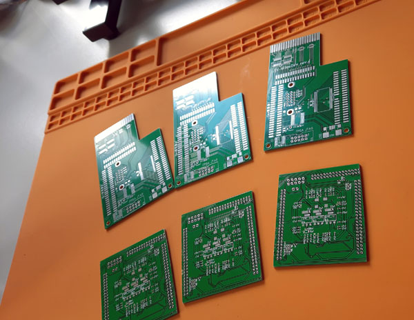 These 3 cartridges are for the beta testers. Man I'm so happy I bought that reflow oven for soldering. I used it for the first time a bit more and the result is really cool. Of course it works fine with the hot air gun too but you have to be really careful otherwise you blow away some components also maybe sometime you forget to solder stuff anyway. And well the result just looks perfect. 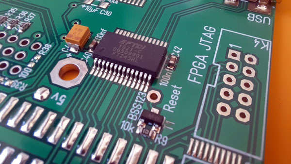 I tested a bit what I can solder in it. I thought maybe leds are a problem but tried today for the first time... Works fine... Nice Building up the FPGA board is quite exhausting on the lower side are alot of 0402 capacitors to place these correctly you can see here:  is quite difficult. if you had too much coffee forget it ;) I need to do a break after each placement session... But these small bastards also making problems during reflow. if you reflow the PCB the components are moving a bit and align to the pads. Sometimes it can happen that the 0402 components change their orientation and directing upwards. This is really nasty because you have to solder by hand these components again. Bla. Odd is this only happens to capacitors not resistors. I guess this is because the shape of the capacitors. Maybe this also happens because of my soldering paste. I used a new box and this one is alot more liquid. I think maybe the capacitor does not have full contact on one side to the soldering paste. Have to test this next time with the new box of soldering paste (only used the old one with the 0402 parts) End result today is this: 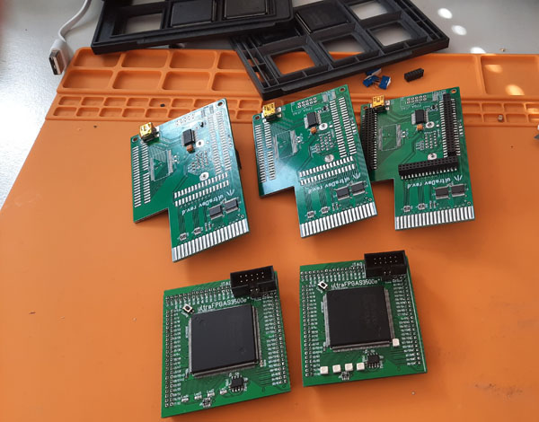 Unforunately I couldn't finish them this weekend. So finishing next week will be hard last week before my vacation at work this is mostly a bit stressy with over hours also need to pack bags for the vacation... Anyway |
|
05.06.2020
ultraDev
|
Tested the folder share a bit today and removed quite a few bugs. Also tested a bit what is the biggest volume I can create. Currently it's 512mb hm this is alot more than I thought. Ok using 8k sectors increases the size alot. Unforunately bigger than 512mb is currently not possible somehow there are quite a few short sign bugs in Tos anyway should be enough. Updated the docs for the next release. So I'll test in the next days and I'll do a release hopefully before my vacation which starts on next friday. |
|
29.05.2020
ultraDev
|
Hm the last days haven't been very productive. I build in one bug after another. The hd implementation worked alot better. Mostly with smaller fixes it worked fine. But this meh was a real pain in the ass. But now it's working again. I was working on something I'm shifting since monthes. The old version was only able to work on 4mb because of the direct direct addresses and stuff. That was quite a bit of work. Also the cartridge needs only as much memory as it really needs. Before it has been about 240kb. Yeah 240kb because of lazyness in calulation ;) Now it's 20kb. Also started to include Tin's and ggn's new Bugaboo (which needed also some changes to be flexible). But Bugaboo is not fully tested yet. Anyway I'll do in the next days. I downgraded my STE to 2mb to test and it worked fine now. This is cool. Besides I'm using now the system 8x8 font to save some cartridge space. I want to include later a small crash handler which can be installed by using the cartridge library which shows the call stack with symbols. Just did a short test a disassembler would fit too. But anyway a future feature. Used the cartridge to code a bit yesterday. I was working on an overscan with sid. Nice coding without touching the Atari ;) |
|
23.05.2020
ultraDev
|
Having a weekend off from my girlfriend so time to ...do things ;) I could not resist today had to try out of I can speed up the stuff again by sending clusters instead of sectors. Seems with 8k sectors -> 16k clusteres it's not getting faster alot like it got with smaller sectors... A bit sad but anyway 600kb/s transferspeed is ok I expected alot less... Seems alot of demos clearing the entire memory. That made quite some problems with the my hd driver (so far the demo loads during the demo runs) because I need some ram to store the old calls for the hdv routines. But I'm now saving them just in the FPGA. This helped alot to get demos to run. Currently all is working (what I've tested of course) except of Drone and Hires from Paradox. Drone is clear because the HD emulation is too slow. Hires dunno why anyway... (hm seems it only works from floppy)... Ah Signals (with streaming music) from dhs works too... niceness... And besides this no crashes anymore I tried out today to share a folder to the Atari from a folder which is shared from my Raspberry worked so far ... nice . But of course it's not possible to recognise changes in the folder since I'm using Windows functions to recognise and this seems not to be possible to use on unc volumes...anyway but still funny that this is working... Speaking of Raspberry. I had today a look to my power supply of my Raspberry (using it for git and stuff) after running some weeks the sd card was always filled with crap.  Hmm great. This is a strong power supply done esp. for the Raspberry. So better to check them from time to time ;) Good that it didn't light my house... |
|
22.05.2020
ultraDev
|
While I was watching the Outline live stream I optimised a bit the transfer routines like finding better values for the USB buffers, reducing the FPGA cycles for receiving and copying the sector buffer via movem.l to the destination I could squeeze out again some kb/s Now I'm almost at 600kb/s (measured with HOWFAST). This is nice Sea of Colours is working fine now. Unforunately Drone is still crashing at startup... Hm anyway. I guess I could speed up again around 80kb/s if I would transfer clusters instead of sectors. But well I'll put that on the todo list maybe I'll do later... So next is to make a release so beta testers can test a bit. |
|
22.05.2020
ultraDev
|
Continued the hd folder share today... Now it's possible to change stuff in the shared folder like adding files or adding entire trees. This is pretty cool I always wanted to do this. Well I've been using Ghostlink for a while years ago. This was quite a cool thing back then. Hm about 15 years time ago I had the idea hm why not doing this via USB this would speed up all alot? But at this time I wasn't very into Atari ST system coding and hm I even didn't know how to add a volume to the desktop. Mostly when I did stuff on Atari the first thing I killed was the system... And well after reading the source of a ram disk from the 80's I saw how easy it is to a) add a volume and b) reading from a virtual volume. Good that Atari added some memory pointers to inject stuff. And besides I wasn't able to do the hardware for this kind of stuff. Well at this time I used a 80c51 like 8 bit cpu which was let's say really bad... Anyway initially I planned to do changes to the of the fly created drive image by deleting files and adding the changes to the volume. But well I did a time measure now and hm building up the drive image for a 100mb needs about 0.01 seconds (with sdd). Call me lazy but I just build up the volume each time I've got changes. it's fast enough. Small demostration of the folder share: |
|
19.05.2020
ultraDev
|
implemented the scanning of sub folders today. Works quite good so far. Some demos do not work no idea why atm.. Even Sea of Colours works.... ok not fully ;) hangs after 3/4 of the demo anyway... Some bit of debugging is surely needed... somehow some demos crashes with 4 bombs when they exit...hm |
|
15.05.2020
ultraDev
|
Continued the folder share today... Now I can share the root of a directory without subfolders... was easier than expected...
so next is to scan the subsolders... This is fun coding... just small changes with cool effects on Atari side... Volume image build up is even quite fast it's about a second for about 40 mb... But need to do more tests... niceness... Booting up from the hd even a desktop.inf works didn't expected this ... ok you can't save it because of no write support currently but anyway ...;) Hmm somehow there is a loose contact in my hxc floopy emu that sux a bit... Btw... small song advice "tool - the pod"... I like that song... I used to hear that song in a club... but well corona you know ;) |
|
13.05.2020
ultraDev
|
Today I could start my first file from the new folder share... this is pretty cool ;) Ok currently it's not really a folder share more a I create a volume image on the fly and with the provided methods of the classes I add a file to the volume image. Of course the first file was REALTiME.PRG ;) Since I have the ability to test with different sectorsizes I used HOW_FAST.PRG to see how the different sector sizes affects the speed. The results: 1k 250kb/s 2k 320kb/s 4k 400kb/s 8k 520kb/s But why different sector sizes affects the speed? That's because high sector sizes will result is less callbacks to the pc. USB uses some kind of send and receive raster means each callback needs some time before it is send or received. I could increase the speed a little bit by always sending clusters to the Atari but anyway I think this is fast enough... So next is now to start scanning the directory and add these files to the volume image... |
|
11.05.2020
ultraDev
|
Puh that small thing I wanted to test before I can release the new price turned into a real problem. The new FPGA board has slight different pinnings and I wanted that the firmware works on both revisions. Unforunately I did not get this to run until now. So I have two different versions of the FPGA firmware but this only affects the beta testers. So time for the final price. Check Final price. Beside this I improved the make release script alot. it's now building almost everything that saves time and reduces errors... Also continued the hd folder share included now a file cache to speed up a little but fat implementation is not done yet. |
|
06.05.2020
ultraDev
|
Oki back to the folder share. Currently I'm working on files in a directory means converting a pc directory data into a atari data and in the end hd directory sectors.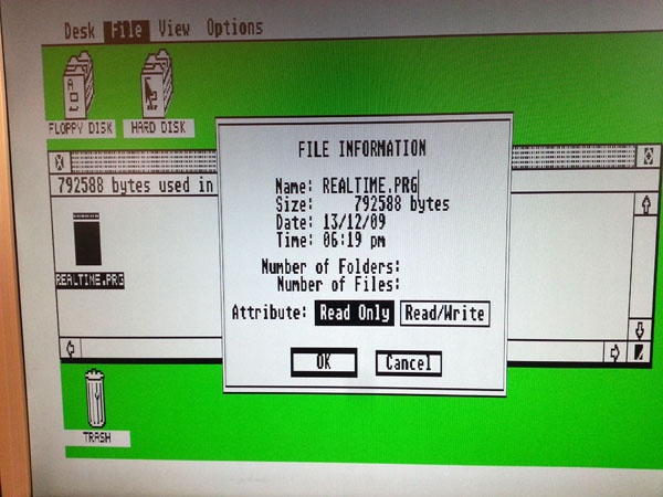 First small success... the on the fly volume image creation works so far and adding a file (without data) to the volume directory too. Next is to include a fat to hold the data. But quite some stuff to do left but enough for today I'm still ko from my last jogging session hm ;) |
|
06.05.2020
ultraDev
|
Really good steps in the last days... The new FPGA updater is done now and needs about 19 seconds to update the FPGA including verify. This is nice I'm feeling alot better with the new updater now... Well the old updater was based on a Xilinx source and hm it was really hard to understand whats going on there. So the new updater is fully done by me and it's just a source which is talking to the prom via SPi. I was working a bit on the make release scripts well before I had to do quite a few things by hand esp. creating the programming files for the config rom were really a pain in the ass. Now they are auto generated niceness... Beside I fixed really really much smaller bugs, continued to make the HD implementation more flexible well before it was quite a bit hardcoded. Yesterday I continued to implement the folder share from PC. The folder share includes a on the fly build up of a drive image so it's quite flexible to test values for the created hd image. So far I can create an empty volume on Atari so I tried a bit with the values esp. the sector size to see if a "Show info" on Atari shows how big the volume is. The volume size changes that is good yesterday I could create a 150mb volume ... but ... this doesn't mean this really works. Next step is to create the directory sectos out of the shared folder. Really exciting stuff ;) I've got from tin/ggn a new version of bugaboo which works (can't test) on falcon but the nicest is it assembles with vasm. I did the first ultraDev version of bugaboo with Turboass on emulator hm a pain in the ass ;) |
|
03.05.2020
ultraDev
|
Changed the FPGA updater now to write the spi prom directly. Works so far the FPGA boots up with the written config file but need to include some kind of verify or so. Really nice is the update needs about 15 seconds now ok without verify currently but anyway will be alot faster than the old updater. |
|
03.05.2020
ultraDev
|
Still testing the new FPGA board a bit. I recognised it does not boot if a ram chip is soldered on the cartridge. After some hardware debugging I found the problem luckily easy so solve (just a pullup resistor ... puh) and normal usage no problem since the ram is not soldered in by default. So FPGA board is working now. This is quite cool didn't expext it works that good well I didn't do a prototype before normally I need to because I'm not the mega hardware guru ;) Next step is now to change the FPGA update mechanism. The old FPGA board had a Xilinx prom which is not so easy programm. You need to use a incircut programming source from Xilinx which is a bit stressy to use also you need to access the prom via a standard JTAG interface. This is why the cartridge has a JTAG interface included. When I designed the the new FPGA board I changed from the Xilinx prom to a standard spi. The spi flash can be accessed directly thru the FPGA which means I can skip the cartridge onboard JTAG interface and cable. That's nice so the cartridge will get a little cheaper also the new FPGA board is cheaper. But let's see I want to include the new update mechanism before I'll tell the final price. So... time to read the spi prom datasheet... stay tuned |
|
17.04.2020
ultraDev
|
Earlier this week some more FPGA from China arrived: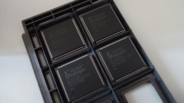 so finally everything arrived which I ordered back in january. Yeah took really long but anyway everything arrived I'm impressed and happy;) Today my new toy arrived:  Hm T962? What could this be? Let's unbox ;) Still no idea? Well if you read the diary a bit I started to use stencils to print the soldering paste, place the components and in the end I do the soldering in one step via hot air by using a hot air soldering thing. This saves unbelievable much of time. But doing it with hot air has some problems: a) if you aren't careful your componets are blown away. I'm using 0402 components (1mmx0,5mm) and this can happen quite easy. And if it happens it a real pain in the ass. b) Another problem is that you sometimes forget to solder or soldering is not 100% done. So the T962 is an oven for soldering. But before you can use the T962 you should really add some mods (like installing a custom firmware, cold junction mod, exchanging internal tapes and adding correct grounding, and changing the fan) otherwise it's unusable, unsave and surely even toxic fumes because of the tape... But why buying such a device ? Because it's cheap and the changes aren't so heavy to do and after it it seems to be a pretty nice oven for home stuff. So before I can use it I opened it:) How it should be ;) Updating the firmware: 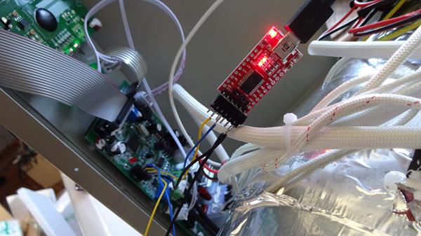 Luckily I had a USB to serial thing (red PCB) to use for the firmware update. So next was to calibrate the temprature. That was quite a bit stressy. I didn't met it 100% but anyway it works so far. First PCB I soldered in the oven: 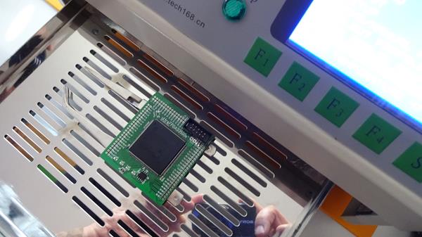 Worked fine so far for the first run. Everything is soldered correctly. Nice nice that saves of course time to build up things... |
|
02.04.2020
ultraDev
|
Seems I have a run currently... Thuesday the hd implementation started to work today I build up the new self made FPGA board. And? it works fine that's pretty cool. Looks like this: Oh just seeing I should clean the PCB a bit ... anyway... On the left you can see my new board on the right the old Waveshare board. Unforunately I forgot a 5V power trace on the PCB (the cable on the left side) but anyway seems that's the only mistake I did... Main differences between these two boards are: a) my has a better decoupling for the power lines b) FPGA updates are easier since the FPGA is booted with a SPi prom c) it's cheaper but more work for me to build up. Have to build up another to see if I can savely produce the FPGA board and how long I need to build up. |
|
31.03.2020
ultraDev
|
I could get the new feature to run today. it's a hd implementation. Have a look to see it in action. Sorry for moving the mouse with the keyboard ... currently I do not have a mouse for my atari... Yes again realtime.prg and blubba.prg ;) I use these mainly to test a) they are big and b) they made most of problems during development. All is in a beta state currently. The hd implementation is a hd image placed on pc. ultraDev adds a volume C to the Atari desktop (plug and play) and you can use it as a hd. Do not wonder about the cartridge volume it's added when you create a cartridge which is not started at reset directly. Currently the hd image is not mega big around 18mb but it's possible to do about 512 mb didn't test yet. For this I need to do a tool to create a hd image anyway. Was alot easier than expected. Browsing the directory worked quite fast but unforunately it always crashed when I started a PRG-file. After reading alot and debugging I remembered I read that TOS only supports 512 bytes sectors. My image has 1024 byte sectors Yep and that was the problem if you reallocate the sector caches it works fine... great ;) To add stuff to the image you can use for example steem. Just mount it add stuff and start up the image with ultraDev. How does it work? You can start the ultraDev command line tool in a server mode means it does not end and serves all requests from the Atari. it's in a early state with no write support I'll add soon. Also some demos do not work like drone or sea of colors (main reason of doing this because I wanted to see it on real hw ;) ) have to trace down why it crashes... But I'm happy except of some demos it is working quite good. Not mega fast about hm I guess about 200-300 kb per second. But with a bigger sector size it will get faster... |
|
30.03.2020
ultraDev
|
Yay... Vacation started today so enough time build up the first FPGA board... So I did today first stuff I've tested worked so far. Uploading the bit file, booting from spi, USB communication and leds are working. That's nice! Puh I'm happy that works so far ;) esp. because a) I did the PCB without doing a prototype and b) well I ordered FPGAs in china and I was expecting maybe fakes. First time I soldered with the sencil hot air technique a 0,5 pitch iC (the FPGA) it worked but have to reduce the pads size a bit to print a little less soldering paste to the PCB. After soldering there were quite a few soldering joins between the pins. Also placing a chip with 0,5 pitch on the PCB isn't easy somehow. if you didn't place it correctly and you have to shift it a bit the print of the soldering smears over the PCB and it's harder to see if the iC is placed correctly. But still less work doing it like this then soldering all by hand. Looks like this upper side: Lower side: Of course this is not the version for the cartridge this is the full build up for some experiments. I'll do a second one this week to see if it is working with the cartridge too. |
|
28.03.2020
ultraDev
|
Some good news ;) Finally the FPGA arrived today: 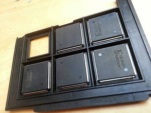 But took really long to get here about 9 weeks. I guess since the shut down in China because of the corona virus alot of snail haven't been send. Anyway it's here now that's cool... This is really a perfect timing my vacation starts next week to enough time to build up the first fpga board. Keep the fingers crossed it's working ;) |
|
20.03.2020
ultraDev
|
No update for a long time ;) Well have been a bit lazy to update the page. But quite a few things happened. New FPGA Board in January I started to design a FPGA board which is compatible to the waveshare board. Since the waveshare board is quite expensive and well dunno if they read the datasheet of the FPGA at waveshare but decoupling capacitors aren't really how Xilinx suggest them. Looks like this: 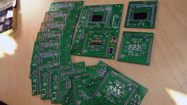 As you can see the FPGA board is quite a bit bigger than the old one. This is because I wanted to create a FPGA board which has dac, switches, sd-ram, vga and usb on board for my future project but it should be also usable as a FPGA board for the cartridge. So on the left the smaller ones are the same PCB but the left and right is cutted. Small close up of the cutted board for the cartridge: 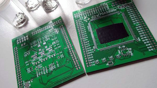 The PCB are again from china this time from JLC PCB but pretty good quality again. But took quite a while to get the PCBs. When I ordered corona virus just started in china. So pretty understandable that they have other things to do. But they arrived. Thanks guys ;) Unforunately I can't finish the FPGA board to test since the FPGA from china didn't arrived yet. if the board is working so far the cartrige will get a little cheaper. But let's see... if it doesn't work ... not ;) Creating selfmake stencils Soldering the PCB can be done the old way like iron and solder or a lot easier method using stencils. You just print the soldering paste on the PCB with a stencil and then you place the components to the PCB. in the end you heat up the entire PCB and all gets soldered. Pretty cool technique and works really good. Well I want to use this technique for my self made PCB too but how do I get the stencils? For this bought a cutting plotter: 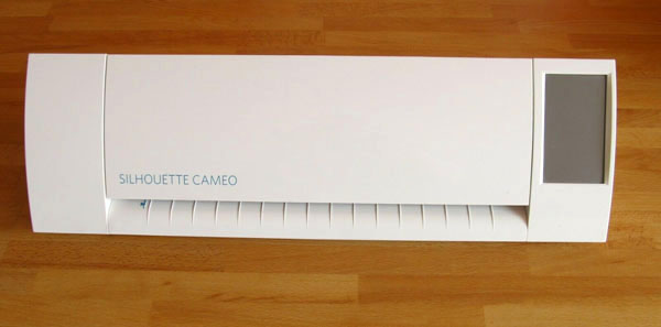 This cuts in a transparent foil the pads so you can use it as a stencil. Pretty cool... There is a tool esp. for creating these stencils with a cutting plotter but getting this to run was a real nightmare. The printer didn't start to print and ended up in debugging and chaning the python code. That took light years. in the end I got it to run. Soldering for the lower side of the new FPGA board done with the self made stencil: Tbh I'm a bit proud... the soldering looks almost perfect ;) Beta testing Tin was testing the cartridge on Mega ST including the reset cable. He said it's almost working perfect. On other systems aren't too much tests done yet. On Falcon it seems to work including the reset cable. Tin and ggn are working on a more compatible Bugaboo which is working on Falcon too. New release After all these hardware things I started to work on the 0.51 release since a few days. Already fixed some bugs and it's now possible to send data max. 16kb via the command line tool from the pc to the Atari. Also started working on a new feature. But let's see if this works out so far ;) That's it so far ... stay healthy ;) |
|
06.01.2020
ultraDev
|
Number 3 is alive... Ok almost at least soldered but not tested yet. Build up worked pretty well. Damn that hot air technique soldering is so cool anyway....I'll test tomorrow too tired today. Well work started today and had a longer Bloodborne session yesterday...;)
|
|
02.01.2020
ultraDev
|
Prepared the first release today it's downloadable in the files section. if you want to have a look to the docs and 68klib and stuff... ggn's FPGA arrived some days ago. With some luck the ultraDev PCB should arrive today or tomorrow. |
|
30.12.2019
ultraDev
|
Yesterday I tested a bit the fpga update. installed the drivers on fresh laptop with no development stuff installed and did a fpga update. Seems to work. Puh ;) Also did some scripts for doing a release which copies all stuff to a directory. Unforunately there are still quite a few steps which need to be done by hand anyway. Today if nothing goes wrong I'll send the first PCB to ggn to beta test a bit. Let's see how this works out ;) Oki that's it for 2019 and this project. I Hope you have a good start into 2020... |
|
28.12.2019
ultraDev
|
Did a bit of tuning on the USB transfer routines today. I can transfer the realtime.prg demo which I used to demonstrate the cartridge speed (see pictures) in 0.8 seconds instead of 0,94 seconds. This is a speed up of about 15% so the transfer speed is now about 967kb/s. This is nice ! The 68k library is now done. Added some nice printf like hex value printing means you can print a string like "bla bla %b %w %l" and the print routine replaces it with the hex values which are passed via a-regs. You can recognise the cartridge clean, getting the version numbers of both fpga and 68k rom now. But I recognised the cartridge 68k code needs some cleanup ;) I'll do tomorrow. So from the stuff I can do here I'm almost done now. Ok getting Bugaboo to work on every platform and getting the cartridge to run could be some work anyway. Time for some Under Construction live stream ;) |
|
27.12.2019
ultraDev
|
Yay user manual is done... 11 pages of bla bla. I'm really happy this is done. Ok need to read again tomorrow but anyway. So enough for today. Tomorrow I'll do the last things on the 68klib and then I think I'm done to let the beta tests see if it works so far... |
|
27.12.2019
ultraDev
|
X-Mas stress is over so time to continue ;) Changed the font for the debug screen today. I found it hard to read with a bit of distance to the screen. Maybe my old eyes but anyway ;)... Today I included a terminal which means you can print out text and the stuff scrolls up. Looks like this: 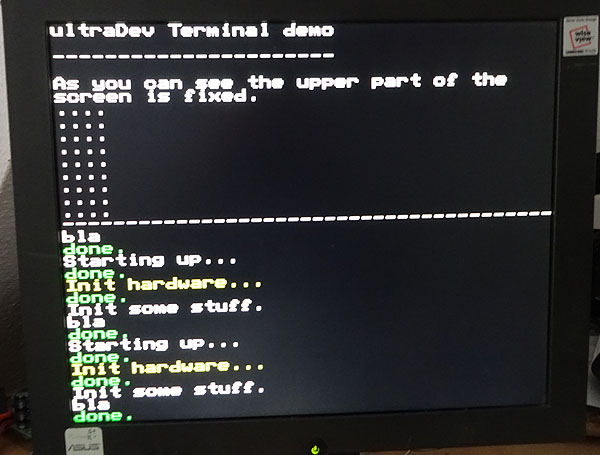 This is also part of the examples. With the terminal you can create at the bottom a scroll area maybe useful if you want to display static stuff at the top. But you also can scroll the entire screen. During init you set the starting line of the terminal. So the debug screen is done now I think. Also the 68kLib is nearly finished. Only have to code a cartridge detect, getting the version numbers of the 68k/fpga firmware. Also providing a save way how to get the pointer to the jump table. The jump table is used later for example for loading stuff after the programm is started. I'm planning to include some kind of disk loading so you have a disk image on your pc and you can do some kind of trackloading from pc during development. But this is a future feature and currently not included in the initial release. Besides I started to write a user manual... Hm really exciting... Ahh can you hear that too? My PS4 complains and wants to get played ;) Bloodborne hm I guess I need to do a break ;) |
|
23.12.2019
ultraDev
|
Productive day today... Continued the 68k service library routines for the cartridge I think most of the stuff is done now. To ensure for a release all is working fine I started a few cartridge examples and to show how to use the 68k library. One thing was nagging me. Some time ago I skipped the bitmap mode for the debug screen because there was not enough memory on the FPGA left. I really would like to have a bitmap mode but doing it with the normal resolution in 40x32 the image would be really small. Yesterday on the couch I had the idea well I'm using an FPGA so I could double each pixel to fill the screen a bit more... Well no problem! Looks like this:  The bitmap mode can display an image of 128x128 pixels. Not impressive but anyway better than nothing... This is part of the examples how to display an image. So the debug screen is pretty close to be finished now maybe here and there some additions to the video chip most of the ppl will not need but anyway ;) |
|
23.12.2019
ultraDev
|
The timing issue is gone niceness... So I continued the debug screen... included some new features like the possibility to get the x/y raster beam position and setting the back ground color. Before only black was possible. in combination of raster beam and back ground color it's now possible to do raster lines. Ok no one needs but as I said earlier doing the debug screen is the most interesting part for me to code also a great learing example how to do things. I'll include some more things I think. I always wanted to code a "video chip" that's so much fun to do. Besides I started to code a 68k lib with service routines for the cartridge like handling the debug screen features and detecting the cartridge and stuff... Unforunately half of the day I've got migraine yesterday :/ This is no fun ended in laying on the couch in the dark with hearing some music. Damn that's so unproductive anyway. So let's see what the head says today. Currently looks good and hopefully I can do more than yesterday... |
|
21.12.2019
ultraDev
|
Back from the vacation... Was nice really relaxing... Had a look today to a timing issue I have since I included the vbl flag for the VGA screen. VGA clock runs in 54Mhz normal things run at 100Mhz means I cross clock domains. First time I used a signal which is generated in other clock domain. Seems the timing check always gives a timing error then. The solution is just to ignore these pathes it seems. I'll try tomorrow... Btw. Tested ggn's ultraDev PCB now for some days. I think I can send it next week. |
|
12.12.2019
ultraDev
|
Ah well ;) I could not resist recoded the debug screen output today and now with state machines (what a wonder) all is fine and working. I knew if I would take that undone thing into my vacation I would think the entire time about it. So this was to get the head free to relax ;) But really cool what I have learned because of the project in the last weeks in FPGA things. it's always good to have a concrete problem to learn stuff. Sure maybe not that interesting for most of the ppl because they do things on emulators anyway. I have been working quite a while with Tao a year ago on a vscode plugin for 68k coding including clock cycle counting or register usage of the selected block and parsing the source to have a more comfortable editing like jumping to the source when you click on a bsr label. it's almost finished after that project we will finish. This is how the idea was born to start stuff directly out of the vscode. The development plattform I ever dreamed of. I just remember when I've got my first Seka version on Amiga in 87 how happy I was. Just changed from c64 to Amiga and wow I an edit a source ;). Before I only coded in Smon a debugger on c64 no source if you forget an instruction damn ;) But funny how the things changed for a long time Turboass have been my fav. development plattform I could not image a better thing... I met markus fritze once in a small computer shop in hamburg a nice guy showed me his turboass in a beta state and the speed holy shit... But took some time till I used turboass alot at this time archimedes was my plattform But tbh vasm annoys me. The vscode plugin needs vasm currently but hm maybe I need to have a look to rmac and add the needed features to it... |
|
11.12.2019
ultraDev
|
Tried to fix the debug screen problem today... Ah well ;) I did it without state machines. I knew that how I did isn't good and to fix the last bugs is too heavy logic. But no heavy task I already planned to recode it... I think this is a typical c-coder problem if you are a beginner in FPGA things not to use state machine. Normally I don't do was a try and didn't work so always use state machines if you do stuff. I'll note it on a post it for future ;) I think that's it before my vacation. Need to prepare some stuff for the vacation also my Ps4 wants to get played ;) anyway ... Going to Boltenhagen (Baltic Sea) in a few days for a week. This is how it looks like:  A small village to cool down from stress in the winter time there is really no one at this time. in the summer time it's filled with alot ppl visiting the beach. So next week will be "full" of no computers, no internet, no tv, no telefone, no atari, no work, no pizza (damn) and stuff... |
|
10.12.2019
ultraDev
|
Luckily today was alot better. Number 2 lives: 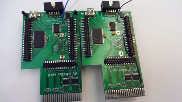 On the left the PCB for ggn. But I'll not send it before x-mas I think. Want to test it a bit before I send ;) Also my vacation starts soon and I have to prepare some things before like pack things and hm maybe getting some x-mas presents ;) Build up worked quite good. Learned alot with the "new" hot air technique and it's getting better. One thing is a bit stressy currently. After soldering with the soldering paste the PCB is very sticky and hard to get off even with alcohol. it's like a small film of something on the PCB which even avoids the connectivity of the PCB connector to the Atari. Have to google a bit how to remove this shit... But anyway number 2 is working that's fine... |
|
10.12.2019
ultraDev
|
Ah well yesterday was these kind of days nothing really worked. I was searching phantom bugs and bla. For example I'm using a floppy emulator and if it's not connected it seems the cartridge is not started.. if you connect it works. So I was searching first I thought it was the new build up of the cartridge ... Have to check the TOS sources again later if this is really the reason. I think if there is no floppy the TOS just do not call to the cartridge because I'm using the entry point directly before the floppy boots. Means no floppy no call or so. And some other unproductive stuff. So I stopped working after a while was better not to destroy stuff ;) Besides as you know the cartridge needs a cable from inside to preform the reset. So I checked the schematics of the Ataris and searched where the cable needs to be soldered. But somehow this is stuipid dunno if ppl want to solder a cable to their Atari this means you need to open up and stuff apart from that dunno if ppl are able to solder... Also quite a bit of work for me to find the correct positions maybe there are different revisions of the boards? Hm ... When I was in bed shortly before I fallen asleep I had the idea hm the Atari could get the information if if it needs to reform a reset. The information is already available since the Atari can check the state machine of the FPGA. So how about a small inserter code to your vbl routine which checks the FPGA state machine and if it is in the Atari reset state it reforms a reset? I think I'll include this of course this does not help if the Atari crashes and not as good as the reset cable but better than nothing. Also needed to include this into the bugaboo but anyway I set it to the todo list. I really hope today is more productive than yesterday ;) |
|
05.12.2019
ultraDev
|
Continued the debug screen today. Unforunately the FPGA internal memory is already 95% means currently hard to realise a bitmap mode for it. Tried alot like reorganising the ram also tried to reduce the upload buffers for the PRG file (which is 16kb) but this slows down the upload so this is out of question to do. And reducing the cardridge rom (which is 16kb too) is no option. So I finally decided to skip the bitmap mode. The other question how useful it would have been. Also I want to save some memory for later use. So uploading a font with 256 chars is enough I think. This is possible and working now. Below a small screen I coded today for the debug screen. it shows the usage of self defined chars.  The red lines are scrolling to upper left to test if a permanent upload of a char works too... To have a clean scrolling I implement a vbl flag from the VGA monitor looks nicer ;) This is what I really love in FPGA coding. if you need something you just include it. But can be also a total nightmare when timing constrains issues appear like before. Also debugging is hard to realise. Yes of course you can simulate to ensure your logic itself is working but that does not ensures it works in the end. For example at the very beginning I had real problems to get the cartridge rom to run. Sometimes it worked sometimes not. The problem was how I grabbed the A1-15 values. in simulation all worked fine but still it didn't work. After some time I used chip scope a tool for the FPGA to do something like a logic analyser for the FPGA pins. And what I saw is? The A1-15 values are changing alot even during the 68k did not finish the instruction. How comes? Hm I'm using a STE (DMA) also the shifter uses the bus to read data and I didn't thought about that. So in the end it was clear why. I need to grab the values when the 68k accesses it. Silly bug anyway. But the debug screen is not done yet. Fixed quite a few bugs today but it still has some. I just hiding them very good in the photo;) The first chars on the left side are wrong I'll trace down next week. But hard to resist not to code more for it like a scroller or a rotzoomer but anyway want to finish that thing. it's like working on an old plattform like let's see what you can do with it. But enough for today... Well bought quite a few new games for Ps4 on Black Friday and they arrived today so need to check them out ;) Btw. next week I'll build up another cartridge from the sample PCB. This one is for ggn to do some more beta tests. I'm really curious if it works on other machines... |
|
05.12.2019
ultraDev
|
Ah great timing issues are gone. I used the wrong clock for the font ram. I'm using a simple dual port ram which enables to read and write at the "same" time with two ports. For both ports you need to specify which clock to use. Reading is the VGA clock which is running at 54Mhz to meet the correct frequencies for VGA display 1280*1024 (108 mhz it is but I only output every second pixel) the other is the write clock which is 100mhz. I used for both 54mhz which produced the problem. Puh ...I already expected a endless search to solve the problem because timing constrains I really did get into yet. Only set one for the clock anyway... This is cool ;) Ok back to work just checked that out... |
|
05.12.2019
ultraDev
|
Continued the debug screen yesterday and included setting the print position and added the possibility to upload a font. Works so far... Unfortunately I have timing constrain failed path in the font upload. Timing constrain failed? Well when you do FPGA things your stuff needs to run at a specific clock means your logic must meet the timing constrains. if something it is too slow you get these errors. When a flip flop switches to the next value with the data must be available shortly before the next clock rises. Then the path to the flip flop is too long you get a setup timing contrain fail. This I have in the font upload which I do not understand currently since the logic isn't that heavy. it has the same logic level like writing a char on the screen. Well I'm really no expert here and analysing is a bit strange since the text outputs of the timing contrains report I do not understand currently ;) Well I'm a beginner and luckily I never had that problems. So I have to investigate a bit I guess the placement of the logic on the FPGA is not optimal. There is a FPGA editor where you can inspect this and maybe change it but didn't understand the tool yet ;) So needs surely a bit to solve this. Ok I could reduce the speed of the design this solves the problem but this is no real solution. I expected this will come esp. when the FPGA gets more filled anyway. A bit stressy now but that's live ;) |
|
03.12.2019
ultraDev
|
Did not finish the debug screen today. Well I could not resist and build up the first PCB sample > if you are interested you can check out the build up blog< Some pictures of the end result 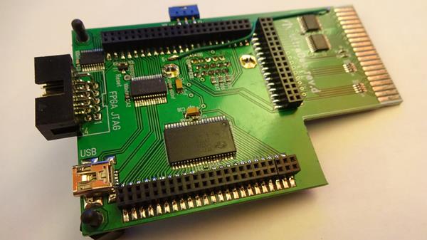 Lower side... 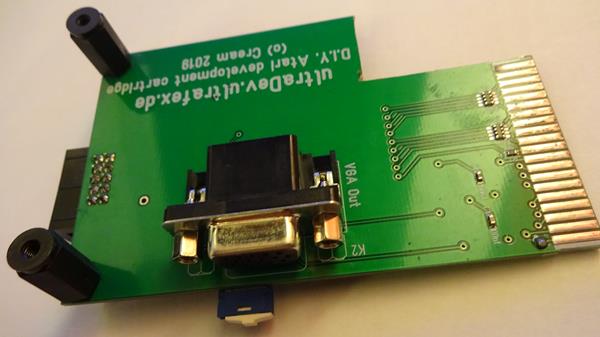 The most exciting moment is which? Yeah check out if it works ;) And it worked without any change.... Coool. Even all features are working with the PCB revision means this is the final PCB layout. yay And besides for the first time using this hot air technique it worked unbelievable good. I think I'll use this for my future projects. This saves so much time and less error-prone during soldering hm and in the end the soldering result looks almost perfect... I'm really impressed. So debug screen have to wait till thursday enough for today. Got some new PS4 games I have to check out ;) |
|
03.12.2019
ultraDev
|
Unbelievable 2... The PCB arrived a few minutes ago. That was fast unforunately expensive too..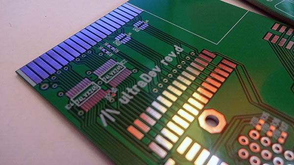 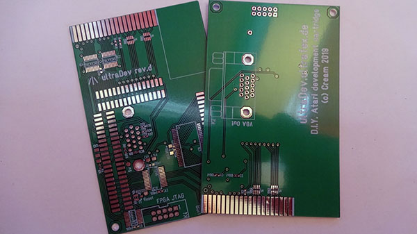 After a closer look. They are looking really nice. Good silkscreen, soldermask and tracks are looking clean... And last but not least the stencil masks for the soldering paste. 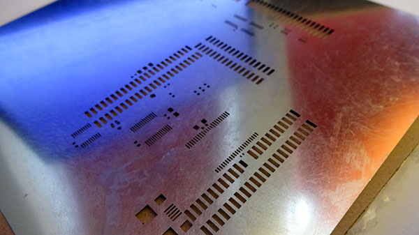
Cool so you know what I'm doing later ;) I'm really curious how that works out with the stencil mask. I'll do a small blog of the build up. But first some stuff at work has to be done... M�h... |
|
03.12.2019
ultraDev
|
Unbelievable... The PCB passed the custom duty at weekend and now they are in Neum�nster which is only 35 km from my home. So let's see how fast I get a message that I can pick it up at the custom office.
|
|
02.12.2019
ultraDev
|
The blue is gone and what would you expect to write to the screen for the first time?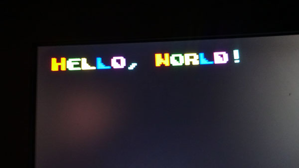 This of course ;) The colors are a bit wrong because of camera. They remember more to spectrum colors but anyway enough for a debug screen. So the text debug screen is almost done now. Writing to the debug screen works like this: move $fb0000+(((%111<<8)+($41-$20))*2),d0 (hopefully I didn't do a mistake here ;) ) This will write a white A to the screen. Looks a bit strange right and why reading? Well the cartridge port has no write signal. So you need to create your write by a read from a specific address. Each read to $fb0xxx will write the value of xxx to the debug screen and the destination address in the FPGA is incremented by one each time. When you read 12 bit of the address is used. 3 bits (rgb bits) for the color (%111<<8) and the asci value -$20 because the font does not have chars for the first 32 chars. *2 because there is no a0 signal on the cartridge port means no odd addresses are possible. So what is missing now is to set the internal FPGA destination address where to print. But enough for today maybe I can finish the text output tomorrow. Hmm unforunately I did a mistake in the calculation for the debug screen bit map mode memory. I guess the memory will be too low for a full bitmap map anyway. So I'll include a font upload from the Atari I think. |
|
29.11.2019
ultraDev
|
The debug screen slowly starts to work.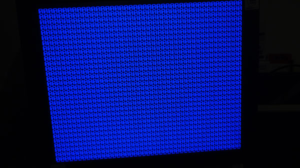 Nice blue btw. anyway ;). So VGA output basically works so I need to code the Atari interface to write something more useful to the screen. Hm it would be possible to upload a font from the Atari but not sure if this makes sense...Have to think about it... Unfortunately no bigger steps today still not recovered 100% from the cold. Besides I called round about 3 times DHL today for the PCB samples. That sux. Currently it's at the customs duty in Cologne. I hope it passes the customs duty next week. |
|
26.11.2019
ultraDev
|
Today I've got an email from China. included was this picture: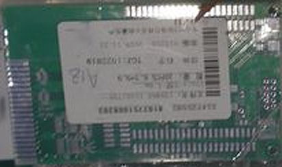 A bit bad quality but shows the PCB samples I ordered are done and on the way to Germany. That's cool. I hope it's soon here because on 14.12.2019 I'm on vacation. But let's see how fast is DHL Express from China. Second picture was this: 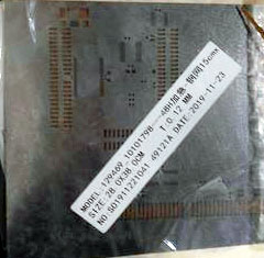 That are the stencil masks for the soldering paste. I'm really currious how that works out never did this till now. But looks really easy if you watch videos on youtube. Beside this only smaller steps with the project having a cold. Started to work on the debug screen and had some thoughts what is needed. I think I'll do a 40*34 text output where every char can have it's own color (8 colors in all). And a second graphics mode with 320*256 with bitplane graphics this one will be b/w only. |
|
22.11.2019
ultraDev
|
Today was a damn productive day. Do you know this? These days when you start to implement something and everything works with the first try? This day I had today... great ;) So what did I do in detail: -Kicked out the resident bugaboo feature since it's not worth the speed. (See below I was talked about it earlier). So the source is a bit cleaner now and even better the FPGA could run more speed if I need. -included new Bugaboo handling and stuff. -included that you can execute Bugaboo commands from the commandline tool -Removed the reset handler from Bugaboo. Makes no sence somehow. -The FPGA updater tool has now more useful texts. Before it was nothing ;) -improved the reset feature a bit. Before I had a delay in the FPGA in which the FPGA waited till the Atari is done with the reset. That's really bad a) not optiomal performance b) the machines are running in a different speed so I had to choose the longest delay. Now it's done with handshaking. -included and tested when the cardridge is not able to reset the Atari (no cable from inside). When you have to press reset is now signalised that all leds are blinking on the cartridge. -Loading address is now shown on the Atari. -Added receive timeouts on FPGA. Normally this is not needed but the problem here was when something went wrong during USB communcation (crash of the commandline tool or you disconnect usb) you had to press a button on the cartridge to reset it. All is working pretty nice currently. I have to say that resetting the Atari is a really cool feature. You just Code some steps press run and you can see if it works. Next time just run again and it starts. So my current todo list got really small today for the stuff I can do/test here (only have a STE) means I have only one thing on my todo list left. I have some more ideas left to include. But the feature set I have now should be enough for the first version. So the last feature is the most interesting feature to code I saved that for the end. Doing the debug screen. I love that doing VGA outputs with the FPGA that's fun. Of course getting the cartridge to run on every Atari will be a bit of work. I think the cartridge itself could work fine the problem here is the Bugaboo. But I hope I can send the beta tester (ggn) a cartridge soon so we can test alot more. Btw. I'm still searching better distributors for the components and how to reduce the price for the PCB. I'm now able to order PCB in china or better I already did order a few samples. So let's see if the quality is good and if they are working. You never know ;) But I think the price for the cartridge will drop for sure. |
|
20.11.2019
ultraDev
|
The new prototype is build up and running. But this was quite a bit of work. Well did a mistake during expose the upper and lower layer were shifted a bit. Unforunately you can see this only when you drill the first hole. The holes for the vias are 0,5 mm if upper and lower layer do not fit 100% you hit maybe a track during drilling and that happned sometimes and produced very strange results. That's always the question rebuild it or try to trace down the problem. This time I decided to trace down but in the end it would have been better to rebuild because I needed a few hours to find this and quite frustating if you invested 2-3 hours to build up and it do not work for a long time. The prototype is no beauty but well it works. So I have my final layout ok VGA I didn't tested yet but I'm pretty sure that will work since this is no rocket science and I already did this in other projects. That's nice so I can sleep well tonight ;) |
|
18.11.2019
ultraDev
|
Did alot surfing and investigations how to produce the PCB and optimised how to build up the cartridge to reduce work. Quite a bit of work so no big steps today. Also it's possible to preorder now. Have a look to the menu. |
|
17.11.2019
ultraDev
|
Etched today (hopefully) the final version of the PCB which I'll build up next week. No big changes I used the right FPGA JTAG connector this time, reduced the colors for VGA to 8 and added a better connector for VGA. |
|
16.11.2019
ultraDev
|
Just after I woke up today I had the idea for a small and easy way to speed up again. included it and well... works. Now I need 43 seconds to update the FPGA. including erase it is 57 before it 100 seconds. That's really enough now. That's a speed up by 53x compared to the initial 38 minutes. Niceness. Somethimes it's good to get some sleep ;) |
|
15.11.2019
ultraDev
|
Unforunately what I was writing before wasn't true the update didn't worked earlier that was a mistake the prom wasn't erased. But it does work now ;). Changed to the Xilinx source I was takling about. That source was alot better but still had problems to get it to run anyway. But holy shit this was a real pain in the ass to configure the prom. Speed it quite ok now. Erase needs about 15 seconds and programming the prom about 85 seconds. I could speed up I think by x5 or so but anyway that's fast enough. So the updater needs some more useful texts and it's done... But before a quick git check in before something is lost. Nice ! So I can do things I'm really motivated to. |
|
15.11.2019
ultraDev
|
The FPGA update seems to work now. it has the entire time somehow but I didn't recognised. Normally if you press the config button on the FPGA board the FPGA should boot but it didn't if I switch off and on it boots fine. That's a bit strange anyway. But even if that works (more or less) I'll test something else I found a xapp from Xilinx about updating the FPGA prom from a embedded microcontroller. That source is alot smaller than that commandline tool I use now 68 sources agains 2. This is alot better to handle for speed up and stuff. But puh anyway that was really stressy to include hopefully the other source is easier to include. it should since from FPGA side I do not need to code something because that part is done... But anyway a step into the right direction will help for future projects for sure. This have been always a problem. Besides I'm working on a new PCB revision hopefully the final one. I reduced the VGA output a bit before it was able to do 128 colors a bit overpowered now it has 8 that should be enough. Less to solder ;) |
|
14.11.2019
ultraDev
|
The FPGA prom update is now alot faster 4 minutes almost 10x faster. Unforunately the FPGA does not boot correclty when reading from the prom. Hm that's bad. TBH a bit annoying problem to wait every time 4 minutes to see if it worked or not avoids you to do things you really want to do... |
|
13.11.2019
ultraDev
|
Tried the bit bang mode today and did change something. Still slow like hell. But it's quite logical since the frame rate of usb is 1 ms. Doing a clock needs then 2 ms. So the JTAG interface needs a bit more then just redirecting the bits to the JTAG connector. I already have an idea let's see if that works... |
|
12.11.2019
ultraDev
|
it's alive ;) The new prototype is working so far I did some pictures during build up. > Build up blog part 2 (soldering the PCB). (click)< Looks like this: Unforunately I did a mistake bla... I used the wrong connector for the FPGA (cable on the left side) the needed connector is 10 pins I used the 14 pin version. Hm that's stupid so it's not the final revision... anyway still works but I need to use a adaptor to programm the FPGA. That I have to fix for the final version. So next step is to see if I can a) compile the commandline tool to programm the FPGA b) I need to code a interface for the commandline tool and the FPGA needs to redirect. (Few hours later)...The commandline tool for FPGA programming compiles on Windows now (Unix before).Added my device and changed the FPGA code to redirect. Well basic are working like jtag scan. Programming the prom is by far too slow needs about 38 minutes (never let it run to the end so I don't know if it works or not) anyway. That sucks. Maybe I need to use the bitbang mode of the ftdi chip. |
|
07.11.2019
ultraDev
|
The layout for the new revision c of the PCB is done .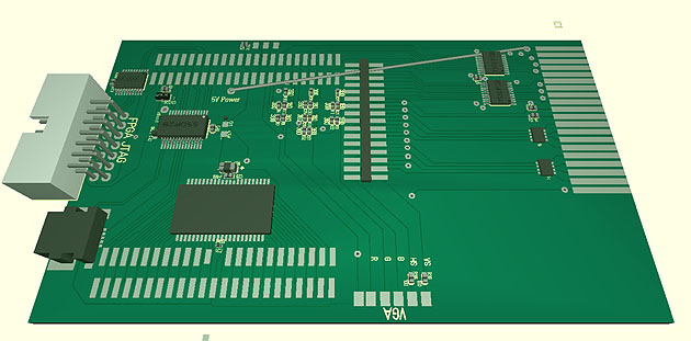 > Build up blog part 1 (doing the PCB). (click)< |
|
07.11.2019
ultraDev
|
I did some speed tests today with the loading of Bugaboo to see how much the memory speeds up the Bugaboo loading. Loading Bugaboo from memory on the board: 0,09s Normal loading: 0,3s The given time is only the transfer to the 68k memory. Not starting it itself. Hm on one hand wow loading via USB takes only 0,3s on the other hand loading from the board memory is only 0,21s faster. Well when I designed the board I thought it's maybe a good idea to have Bugaboo resident in the memory. I didn't expect the transfer is that fast. At the very beginning the USB transfer wasn't that fast but after tuning it it got faster and faster So the main question is now. is it really worth? To gain 0,21s? I don't think so. Furthermore it's the most expensive part on the cartridge PCB. So I'll skip the memory support for Bugaboo... A bit sad for the work but anyway makes the cartridge cheaper. But I'll not fully remove it from the PCB. Maybe there is a usage for later projects? How knows... |
|
06.11.2019
ultraDev
|
Currently I'm working on a new PCB revision which includes the last minutes changes from the prototype. One thing is really stupid. The 68k code can be updated easily by uploading the image via USB. But how about the FPGA bit-file? You only can do if you have a FPGA programmer. That sucks! So I tried to find a solution for this. Then I had the idea. The config prom (which loads the FPGA with the bit-file) can be accessed via JTAG interface. So I only need to have a JTAG out on the board to plug directly to the FPGA JTAG. Luckily there is xc3sprog. A tool which is able to programm FPGA proms via command line and even better the source is included. So I only need to redirect the JTAG pins on FPGA and change xc3sprog a bit. Thats pretty nice. Let's see if this works. The new JTAG interface is already included in the new PCB revision. Next step is to check the PCB for possible errors and then I'll build up a new PCB. |